Roll dispenser

a dispenser and roll technology, applied in the field of roll dispensers, can solve the problems of affecting the quality of roll dispensers,

Inactive Publication Date: 2005-08-16
CONTRERAS EMILIANO
View PDF18 Cites 22 Cited by
  • Summary
  • Abstract
  • Description
  • Claims
  • Application Information

AI Technical Summary

Benefits of technology

[0015]A third embodiment includes a housing comprised of upper and lower housings. A slit is arranged between the upper and lower housings. A blade is supported adjacent the slit by arms extending from the housing. A bar is connected between the arms slightly higher than the blade to protect the user from blade.

Problems solved by technology

Grabbing the roll of paper towel during dispensing often makes the roll dirty.
A person who has been cooking often makes the dispenser dirty by grabbing it during dispensing.
Further, the cardboard box is opaque, so that the remaining amount of sheet material cannot be seen.

Method used


Image

  • Roll dispenser
  • Roll dispenser
  • Roll dispenser

Examples


first embodiment

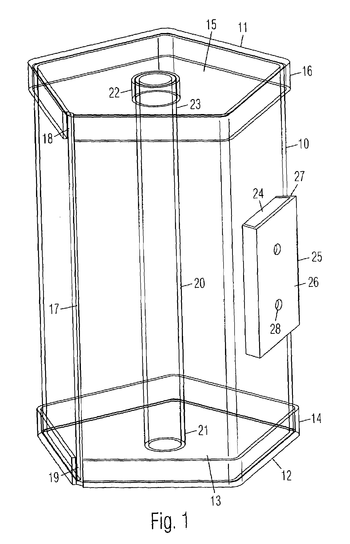
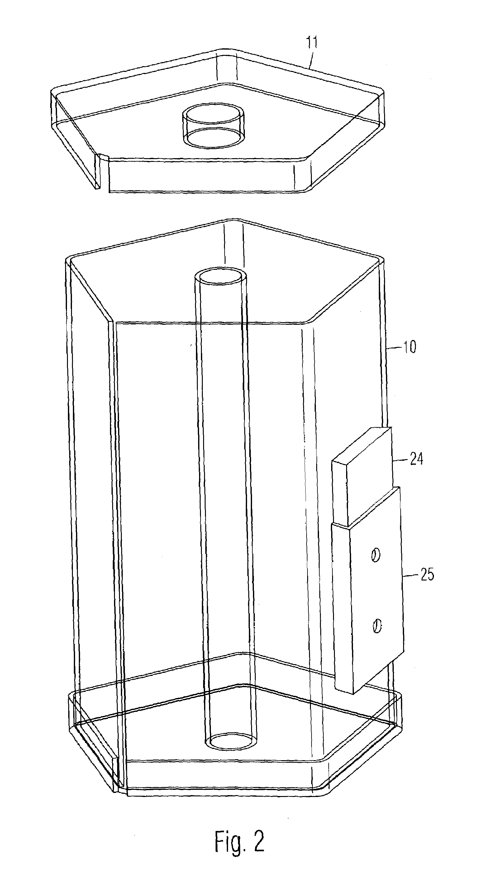
[0024]the present roll dispenser is shown in a side perspective view in FIG. 1. It is comprised of a tubular housing 10 with a first end cap 11 and a second end cap 12. In the example shown, housing 10 and end caps 11 and 12 are transparent, but they may be opaque. Housing 10 is pentagonal in cross section, but it may be of any other shape. Second end cap 12 is preferably comprised of a plate 13 with an integral lip 14 which is parallel to housing 10 for a slide fit. Lip 14 may be on the outside of housing 10 as shown, or it may be on the inside. Alternatively, lip 14 may be eliminated and second end cap 12 may be fixedly attached to housing 10. First end cap 11 is preferably comprised of a 15 plate with an integral lip 16 which is parallel to housing 10 for a slide fit. Lip 16 may be on the outside of housing 10 as shown, or it may be on the inside. First end cap 11 is removable from housing 10. A longitudinal slot 17 is arranged along housing 10. Slots 18 and 19 in respective lips...

second embodiment

[0027]the roll dispenser is shown in a partial sectional view in FIG. 4. It is comprised of a tubular housing 55 with first and second end caps 56 and 57 at opposite ends. Second end cap 57 is fixed to housing 55. First end cap 56 is removable from housing 55 for inserting a roll of sheet material 58, such as a roll of paper towel. A rod 59 is positioned within housing 55 and connected to second end cap 57 for being positioned inside a core 60 of roll of sheet material 58. A threaded shaft 61 has an inner end connected to rod 59, and an outer end positioned through first end cap 56 and connected to a knob 62 positioned against the outside of first end cap 56. A coil spring 63 is positioned between a shoulder 64 of rod 59 and an inner end of first end cap 56. Knob 62 is turned to apply a desired amount pressure against roll of sheet material 58 to avoid spinning it when a sheet is torn off through a slit (not shown) on housing 55.

FIG. 5:

third embodiment

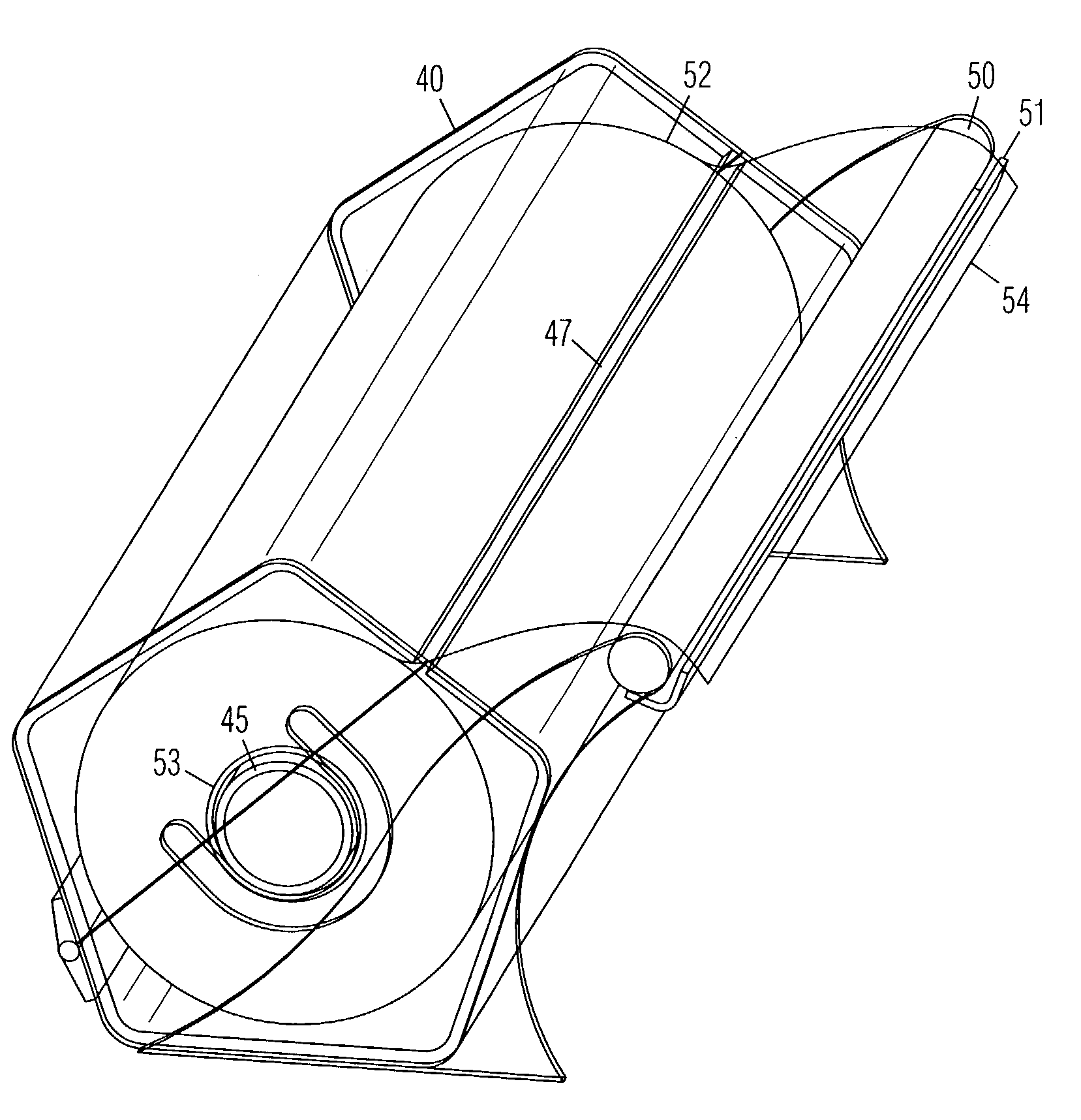
[0028]the roll dispenser is shown in FIG. 5. It is comprised of a tubular housing 40 with end caps 41, which are preferably transparent. Housing 40 is pentagonal in cross section in this example, but it may be of any other shape. Housing 40 is divided into a lower housing 42 and an upper housing 43 connected by hinges on a rear side 44. A rod 45 is supported longitudinally inside housing 40 by a pair of brackets 46 attached to end caps 41. A longitudinal slot 47 is arranged along a front side of housing 40. Slot 47 is preferably comprised of a gap between the adjacent edges of lower and upper housing portions 42 and 43. A longitudinal blade 48 is supported in front of slot 47 by arms 49 extending from housing 40. A bar 50 is supported by arms 49 between blade 48 and slot 47. A top of bar 50 is positioned higher than a cutting edge 51 of blade 48 to protect the user from blade 48.

FIG. 6:

[0029]In FIG. 6, upper housing 43 is pivoted open and rod 45 is removed from brackets 46 to show t...


PUM

PropertyMeasurementUnit
angleaaaaaaaaaa
pressureaaaaaaaaaa
transparentaaaaaaaaaa

Abstract

A roll dispenser is comprised of a tubular housing with a first end cap and a second end cap. Each end cap is comprised of a plate with an integral lip which is parallel to the sides of the housing for a slide fit. The first end cap is removable from the housing. A longitudinal slot is arranged along the housing. Slots in respective lips of the end caps are aligned with the slot in the housing. A rod has a second end attached to the inside of the second end cap in a coaxial position inside the housing. A ring attached to the inside of the first end cap is arranged to support a first end of the rod. A mounting block is attached to a side of the housing. A mounting bracket is detachably mated with the mounting block for mounting the dispenser on a wall.

Description

CROSS REFERENCE TO RELATED APPLICATIONS[0001]I claim the benefit of provisional application No. 60 / 382,736 filed on May 23, 2002.BACKGROUND OF THE INVENTION[0002]1. Field of the Invention[0003]The invention broadly relates to rolled sheet dispensers.[0004]2. Prior Art[0005]Rolls of household sheet materials such as paper towels and plastic wrap are typically placed in dispensers. A paper towel dispenser is typically comprised of a vertical rod attached to base. A roll of paper towel is slid onto the rod to be gradually unrolled. When removing a sheet of paper towel, most people pull out a sheet with one hand, hold the roll with the other hand, and tear off the sheet. A person who needs to use a paper towel often has hands covered in food, grease, dirt, etc. Grabbing the roll of paper towel during dispensing often makes the roll dirty. Further, the sheet is sometimes ripped at an angle instead of along the perforation.[0006]A roll of plastic wrap is typically sold in a lightweight ca...

Claims


Application Information

Patent Timeline
Patent Type & Authority Patents(United States)
IPC IPC(8): B26F3/02B65H75/32B65H75/18B65H35/00
CPCB65H35/002B65H2701/1752A47K10/3836A47K2010/3863Y10T225/285
Inventor CONTRERAS, EMILIANO
Owner CONTRERAS EMILIANO
Why Eureka
Try Eureka