Socket for electrical parts and method for using the same

a technology for electrical parts and sockets, which is applied in the direction of individual semiconductor device testing, coupling device connection, instruments, etc., can solve the problem that prior art does not disclose adjacently disposed ic sockets, and achieve the effect of effective conduct and easy replacemen

Inactive Publication Date: 2005-08-16
ENPLAS CORP
View PDF8 Cites 6 Cited by
  • Summary
  • Abstract
  • Description
  • Claims
  • Application Information

AI Technical Summary

Benefits of technology

[0035]According to the present invention, the socket body comprises an accommodating surface portion to accommodate the electrical part. The height of the accommodating surface portion is an approximately the same height as that of another socket which is disposed next to the socket. And when a plurality of the sockets for the electrical part are adjacently disposed to each other, the electrical part can be mounted over a plurality of accommodating surface portions in such a manner as bridging the accommodating surface portions. Therefore, as the socket of the present invention is different from a conventional socket which accommodates each independent IC package one by one, performance tests for even a long electrical part extending over a plurality of sockets can be effectively carried out in the present invention. Further, the electrical parts having different length can be properly accommodated and tested by changing the number of socket optionally.
[0036]According to another aspect of the present invention, a peripheral edge portion of the accommodating surface portion is formed so as to be positioned at a place close to a peripheral edge portion of the accommodating surface portion of the another socket disposed next to the socket. Therefore, no wider clearance exists between adjacent accommodating surface portions, so that the electrical part can be conveniently accommodated over the accommodating surface portions.
[0038]According to another aspect of the present invention, a cover member is rotatably attached to the socket body and a pressing member for pressing the electrical part is attached to the cover member, pressing portions of the pressing members being arranged in such a manner as lined up in a plurality of rows along a right and left direction. Therefore, the terminals lined up in rows can be pressed effectively to the contact pins.
[0039]According to another invention, the socket body has a contact unit in which the contact pins are disposed, a cover supporting member attached to one end portion side of the contact unit, the cover supporting member having a cover member rotatably attached to the cover supporting member, and an engaging member for engaging with a front edge portion side of the cover member, the engaging member being provided at the other end portion side of the contact unit. And the socket body is divided into three parts—the contact unit, the cover supporting member and the engaging member—. Therefore, there is no frame-like portion on the side portion of the contact unit (on the side of the peripheral edge portion of the accommodating surface portion) so that the adjacent two accommodating surface portions can be disposed close to each other, being able to accommodate the electrical part over the adjacent accommodating surface portions. Performance test etc. of the electrical part can be effectively conducted. Further, in a case where a portion of one of the three divided parts, for example, deteriorates, the deteriorated portion can be easily replaced with good one.

Problems solved by technology

But the prior art does not disclose the adjacently disposed IC socket comprising a plurality of IC sockets on which the long combined IC package unit is mounted to carry out performance testing of the IC packages simultaneously.

Method used


Image

  • Socket for electrical parts and method for using the same
  • Socket for electrical parts and method for using the same
  • Socket for electrical parts and method for using the same

Examples


first embodiment

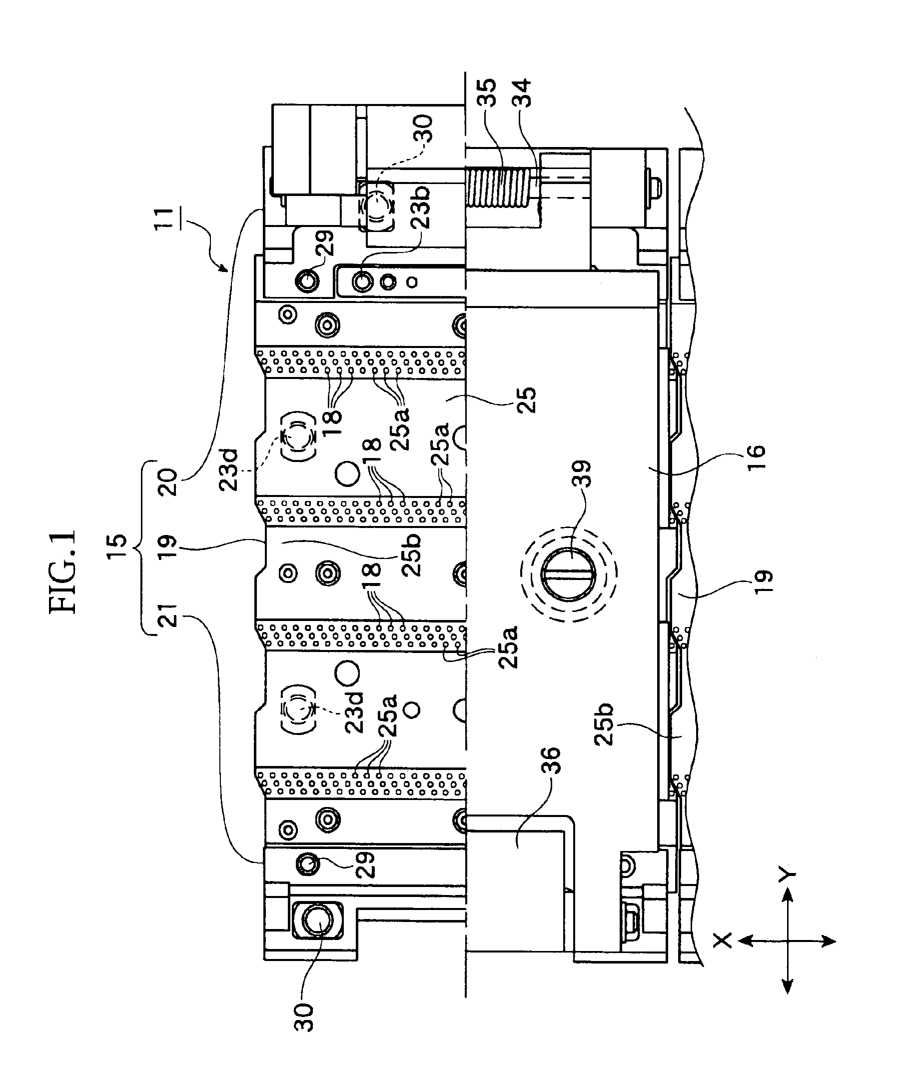
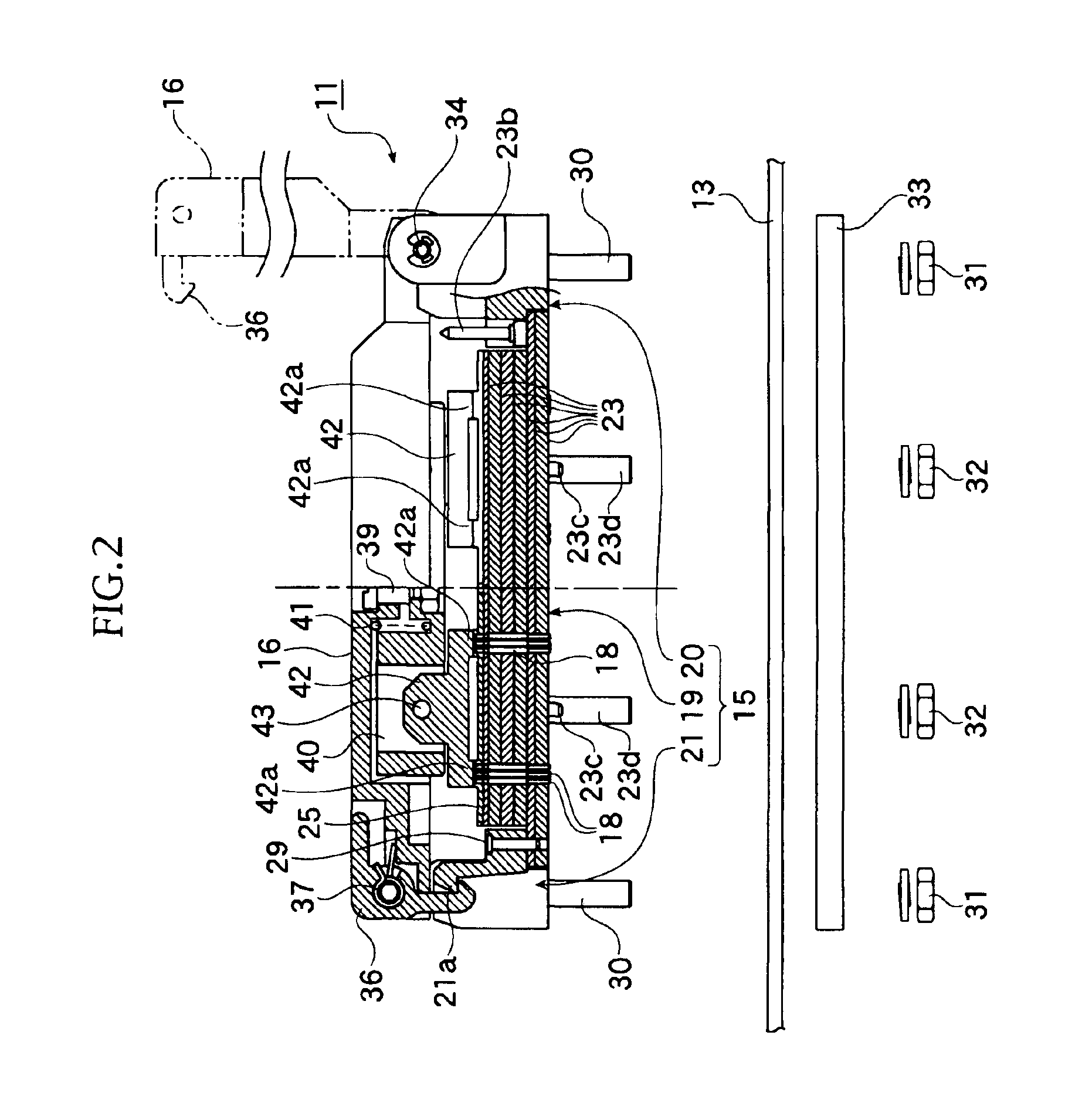
[0059]FIGS. 1 to 12 represent a first embodiment of the present invention.

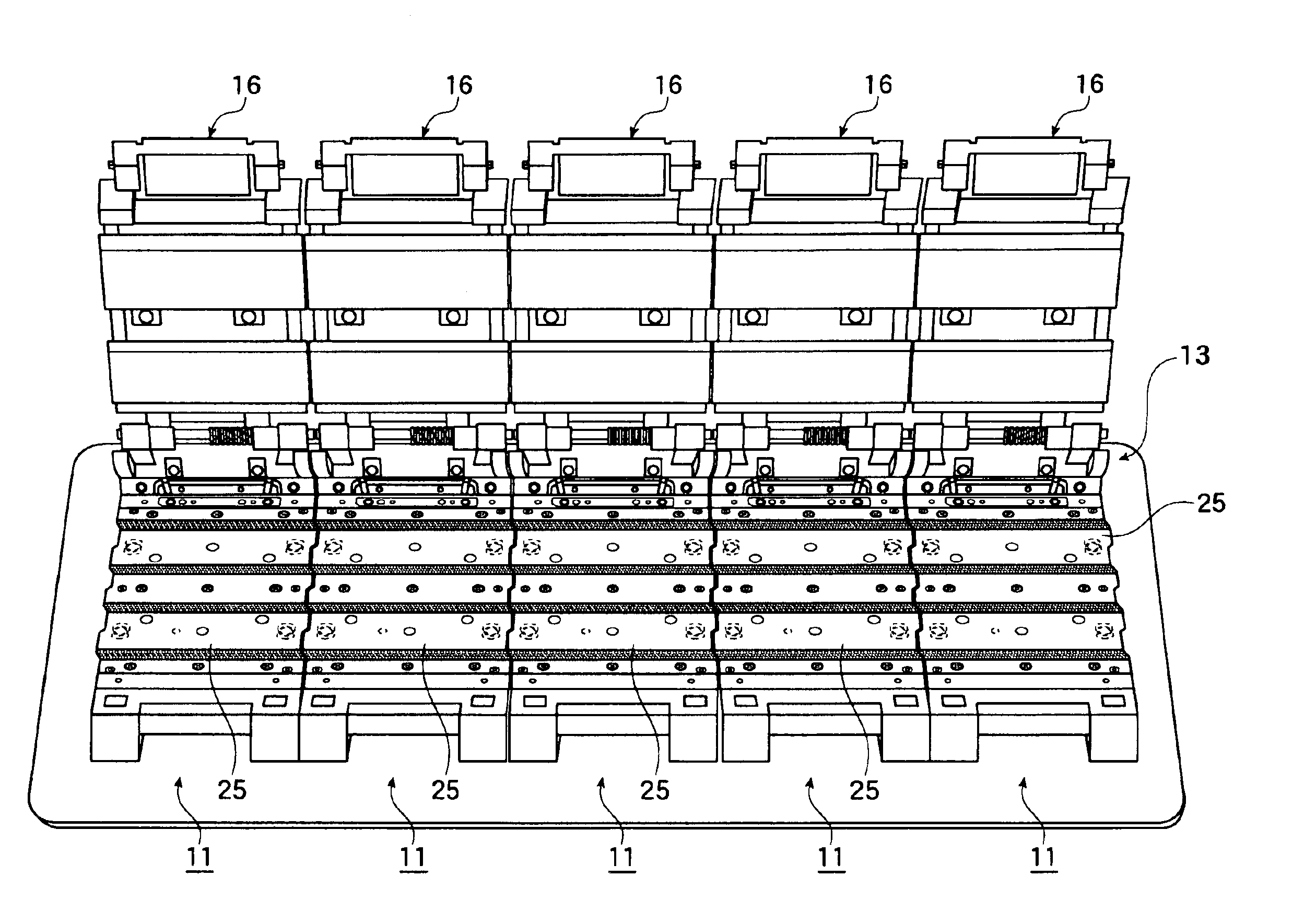
[0060]At first, the structure of the embodiment will be described. Reference numeral 11 in the figures denotes what is called a clam shell type IC socket as a “socket for electrical part”. The IC socket 11 is designed to conduct a performance test of an electrical part by establishing an electrical connection between a terminal of the electrical part and a printed circuit board 13 of a measuring device (tester).

[0061]The electrical parts of the first embodiment are arranged on the IC socket 11 in two rows along a cross direction (X direction in FIG. 1) of the socket and are arranged in prescribed rows along a width direction (Y direction in FIG. 1) of the socket. The IC package bodies are arranged at an interval of certain distance to each other to configure a long unit shape extending toward the socket's cross direction.

[0062]At a pair of side portions of each IC package body along the socket's cross directio...

second embodiment

[0108]FIGS. 13 to 15 show the second embodiment of the present invention.

[0109]The second embodiment is different from the first embodiment in structures of both the cover supporting member 20 and the engaging member 21 with respect to the contact unit 19, and in a structure etc. of the pressing member 42 attached to the cover member 16.

[0110]That is, on the cover supporting member 20 and the engaging member 21, engaging projections 20a, 21b which are engaged with engaging recess portions 19a of the contact unit 19 and the fitting pin 23c fitted into the printed circuit board 13 are formed.

[0111]Further, these cover supporting member 20 and the engaging member 21 are designed to be attached, by a bolt 46 and a nut 47, to the printed circuit board 13, the insulating plate 33 and a reinforcing plate 48 which is used for preventing the printed circuit board 13 from warping.

[0112]Attaching the contact unit 19 to the printed circuit board 13 can be carried out as follows, that is, at fir...


PUM


Abstract

A socket for the electrical part of the present invention has a socket body to be mounted on a circuit board and to accommodate the electrical part and a contact pin disposed in the socket body, through which the circuit board and the electrical part are electrically connected. The socket body includes an accommodating surface portion to accommodate the electrical part. A height of the accommodating surface portion is an approximately the same height as that of another socket which is disposed next to the socket. And when a plurality of the sockets for the electrical part are disposed adjacently to each other, the electrical part can be mounted over a plurality of accommodating surface portions in such a manner as bridging the accommodating surface portions.

Description

BACKGROUND OF THE INVENTION[0001]1. Field of the Invention[0002]The present invention relates to a socket for electrical parts for detachably holding electrical parts such as a semiconductor device (which is called herein as an “IC package”) or the like, to conduct electrical test and examination of the electrical parts. The present invention also relates to a method for using the socket for the electrical parts.[0003]2. Related Art of the Invention[0004]As a conventional socket of this kind, there have been an IC socket as a “socket for electrical parts” for conducting a burn-in test or the like of the IC package by detachably accommodating the IC package as an “electrical parts” on the socket.[0005]The IC socket has a socket body on which the IC package is accommodated and in which a plurality of contact pins are disposed. To the socket body, a cover member is attached to be opened and closed for pressing the IC package.[0006]The burn-in test or the like on the IC package can be c...

Claims


Application Information

Patent Timeline
Patent Type & Authority Patents(United States)
IPC IPC(8): H01R13/22G01R31/26G01R1/073H01R33/76
CPCH01R13/22H01R2201/20
Inventor SHIMADA, HIDEO
Owner ENPLAS CORP
Why Eureka
Try Eureka