

Urethral catheter stent delivery system
a urethral catheter and stent technology, applied in the field of stent delivery systems, can solve the problems of difficult or impossible urination, uncomfortable prostate enlargement,
- Summary
- Abstract
- Description
- Claims
- Application Information
AI Technical Summary
Benefits of technology
Problems solved by technology
Method used
Image

Examples
first embodiment
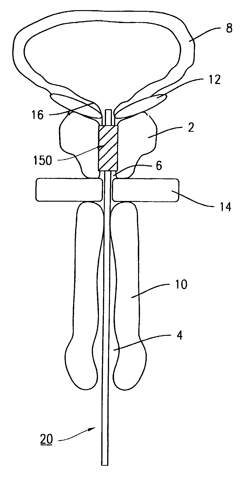
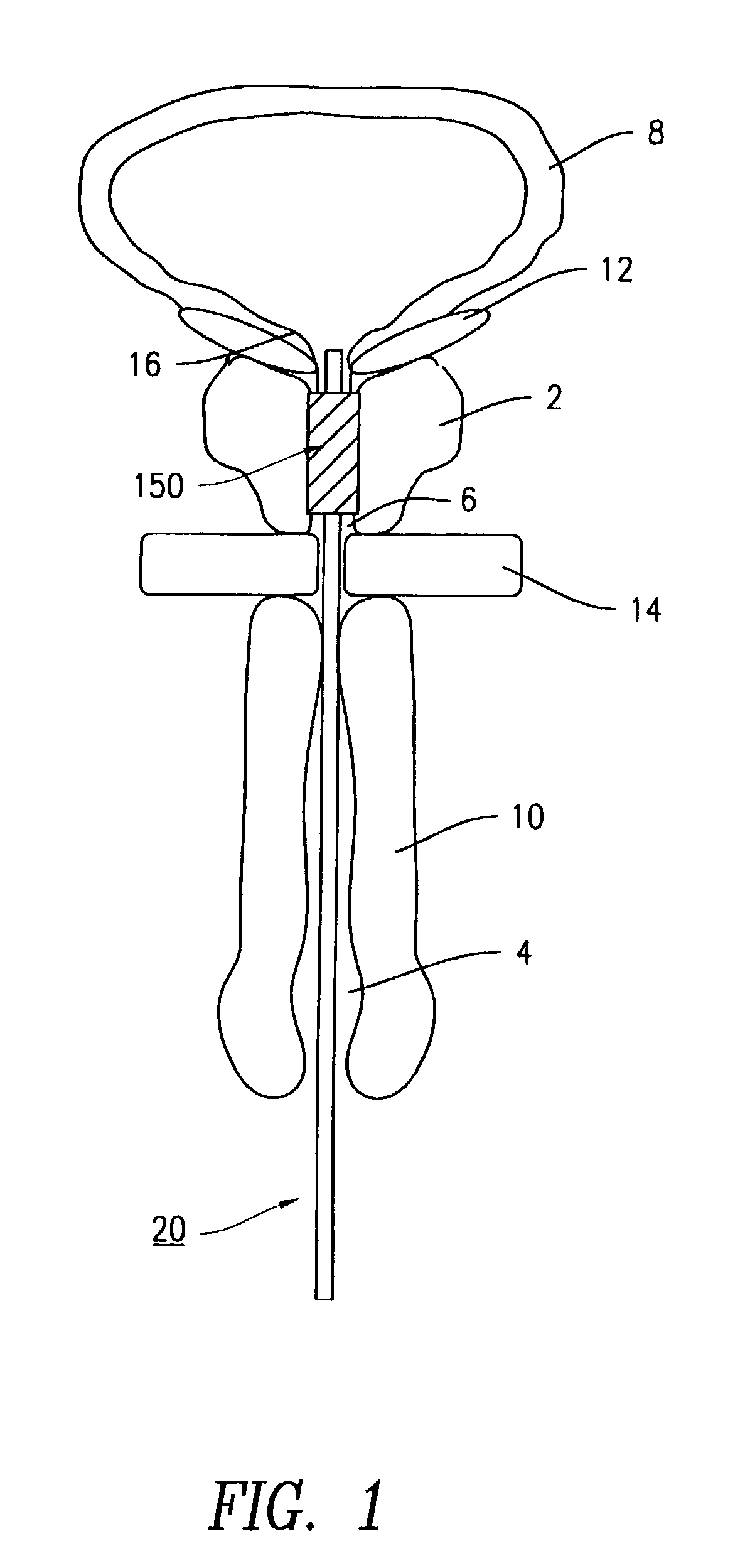
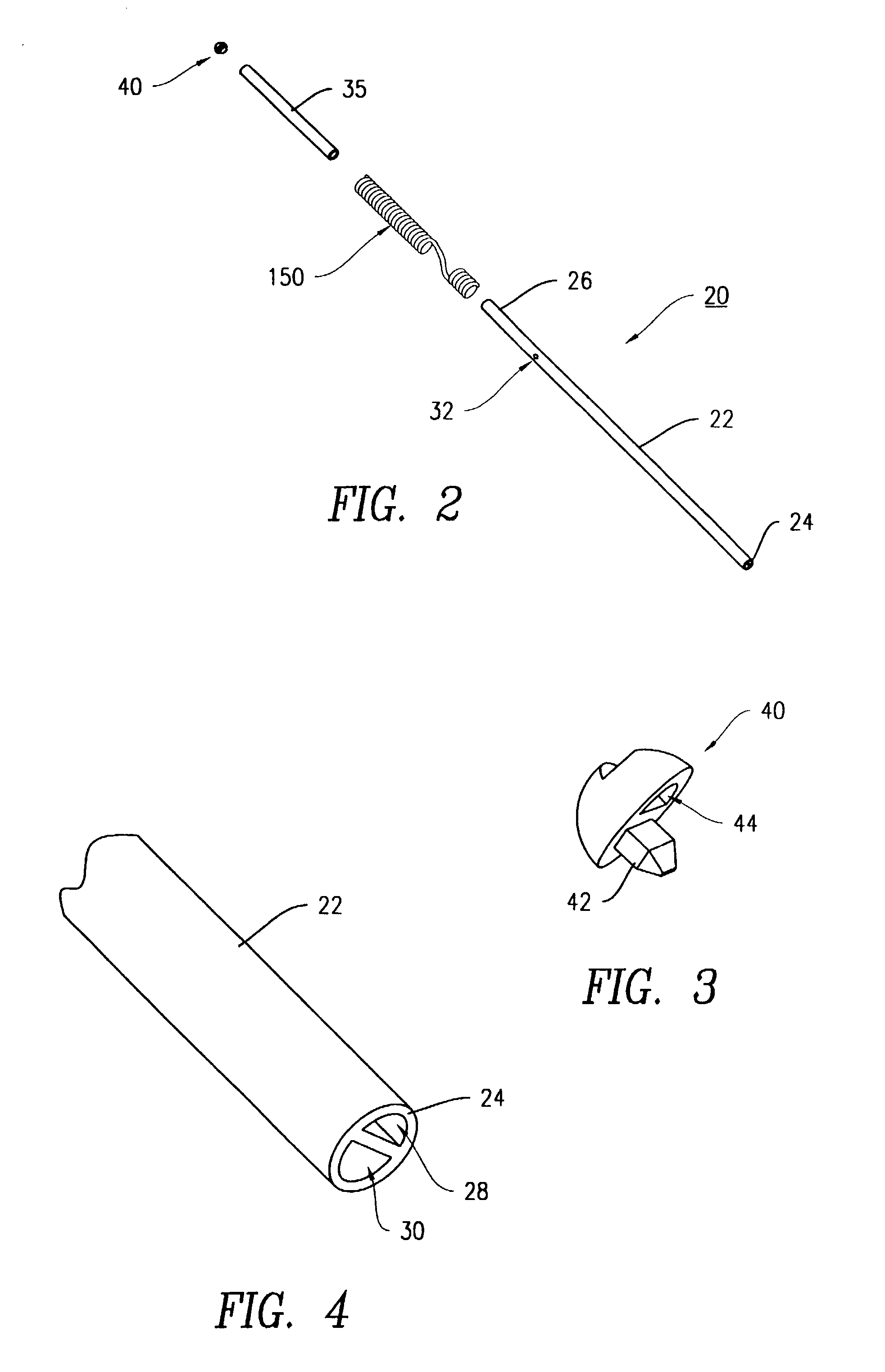
[0044]Stent 150 is delivered to the prostatic urethra 6 by the stent delivery system 20 illustrated in the following figures. the present invention is shown on FIGS. 2–7. The stent delivery system 20 generally includes catheter 22, distal tip 40, and stent retention balloon 35.
[0045]Catheter 22 is a tubular structure with proximal 24 and distal 26 ends, through-lumen 28, stent retention balloon lumen 30, and stent retention balloon port 32. Distal tip 40, disposed on catheter distal end 26, has tip lumen seal protrusion 42 and tip through-hole 44. Distal tip 40 is disposed on catheter distal end 26 so that tip lumen seal protrusion 42 is disposed in stent retention balloon lumen 30 to seal the lumen, and tip through-hole 44 is aligned with through-lumen 28. In practice, tip through-hole 44 and through-lumen 28 allow passage of either a guide wire, or a visualization means to facilitate delivery system placement, through catheter 22 to allow for accurate placement of stent 150 in pro...
second embodiment
[0049]As previously mentioned, tip through-hole 44 and through-lumen 28 allow passage of either a guide wire, or a visualization means to facilitate delivery system placement, through catheter 22 to allow for accurate placement of stent 150 in prostatic urethra 6. A second embodiment stent delivery system 50, as shown in FIGS. 8 to 14, could also be used to accurately place stent 150 in prostatic urethra 6. Stent delivery system 50 generally includes catheter 52, distal tip 70, stent retention balloon 35, and locating balloon 66.
[0050]Catheter 52 is a tubular structure with proximal 54 and distal 56 ends, stent retention balloon lumen 58, locating balloon lumen 60, stent retention balloon port 32, and locating balloon port 64. Distal tip 70, disposed on catheter distal end 56, has tip lumen seal protrusions 74, 76. Distal tip 70 is disposed on catheter distal end 56 so that tip lumen seal protrusions 74, 76 are disposed in stent retention balloon lumen 58 and locating balloon lumen ...
third embodiment
[0056]Although this embodiment of the stent delivery system of the current invention allows for accurate placement of stent 150 in prostatic urethra 6, the user of the stent delivery system of the current invention may still wish to exercise an over-the-wire guidewire placement technique or direct visualization to place stent 150. a catheter 82 and distal tip 100, shown in FIGS. 15 to 17, will allow for this capability.
[0057]Catheter 82 is a tubular structure with proximal 84 and distal 86 ends, stent retention balloon lumen 87, locating balloon lumen 89, through-lumen 88, stent retention balloon port 91, and locating balloon port 92. Distal tip 100, disposed on catheter distal end 86, has tip lumen seal protrusions 102, 104, and tip through-hole 106. Distal tip 100 is disposed on catheter distal end 86 so that tip lumen seal protrusions 102, 104 are respectively disposed in stent retention balloon lumen 87 and locating balloon lumen 89 to seal, and tip through-hole 106 is aligned w...
PUM
 Abstract
Description
Claims
Application Information