CO2 separator method and apparatus

a separator and co2 technology, applied in the field of methane and carbon dioxide separation and recovery, can solve the problems of difficult economic recovery of chemically inert organic solvents, difficult economic recovery of uniform processing and/or equipment, and special complex tasks, so as to increase the operating efficiency of the system and reduce the loss of methane

Inactive Publication Date: 2005-08-16
CONSORTIUM SERVICES MANAGEMENT GROU
View PDF31 Cites 65 Cited by
  • Summary
  • Abstract
  • Description
  • Claims
  • Application Information

AI Technical Summary

Benefits of technology

[0036]Water vapor is removed from purified methane gas in one of two dehumidifying absorbers. While one dehumidifier is dehumidifying gas from the absorber, the other may be regenerating its adsorbent with gas taken from the second separator. The gas from the second separator dehumidifies the adsorbent before being returned to the first separator, thereby increasing the operating efficiency of the system because less methane is lost.

Problems solved by technology

As used herein, the landfill gas contains methane and carbon dioxide in mole percents ranging from about 35% to 65% for each constituent, at combined nitrogen and oxygen content of less than about 10% and trace contaminants that may vary widely in type and amount so as to make uniform processing and / or equipment a difficult task to achieve economically.
This task is especially complicated by the variations in contaminant types and amounts encountered in various landfill gases as well as the gases obtained from a single landfill over a period of time or at different locations in landfill.
Even chemically inert organic solvents may be difficult to regenerate once contaminated because of similarities in the physical and chemical properties of the solvents and contaminants.
Absorbents which cannot be fully regenerated may continue to accumulate trace contaminants until the absorbent becomes saturated and the contaminants break through with the fuel product.
Consequently, some absorption processes often have the disadvantages of routinely requiring fresh solvent and have the potential for permitting toxic contaminants to become present in the fuel product.
Moreover, some absorption processes may not facilitate economically feasible recovery of the carbon dioxide, which must instead be incinerated in a stream containing the trace contaminants.
Adsorption processes may also have disadvantages similar to those of absorption processes.
In particular, trace contaminants from the landfill gas can become permanently bound to the molecular sieve adsorbent causing fouling and blocking of adsorption sites, thereby increasing the pressure drop across the adsorption column and / or causing loss of capacity.
Membrane separation processes for removing carbon dioxide may also have disadvantages.
With membrane separations, a significant portion of the methane may not be recovered, and carbon dioxide recovery may not be economically feasible which means that the carbon dioxide stream containing the trace contaminants must be incinerated.
Membrane processes also have the potential for allowing toxic contaminants into the fuel product and degradation of the membrane by trace contaminants is possible.
While it is known to separate carbon dioxide from methane using a combination of compression and refrigeration, known processes have not further developed this basic technique.
This separation economically impairs any subsequent purification of the carbon dioxide and does not allow for economies in operating or equipment when a landfill gas containing a relatively minimum amount of contaminants is to be processed.
Thus, the prior art has not taken full advantage of the contaminant separation capability of carbon dioxide, and therefore has not efficiently utilized refrigeration and compression to effect separation of such products.
Consequently, refrigeration methods for separating methane from landfill or other gases having a high carbon dioxide content have been regarded generally as being economically unattractive.
The absorbent recovery scheme described here is complex and doubtful from the point of view of consistency.
Advantages of the chemical or physical absorption processes are achieving low concentrations of carbon dioxide in the methane gas; disadvantages, include high capital and operating costs, high fuel consumption, complexity of operations and costly oversized equipment to remove high content of carbon dioxide (30% or more by volume).
Disadvantages include higher initial cost, higher maintenance cost, higher operating cost, expensive replacements of membranes, and costly oversized equipment to recycle and reheat a large percentage of the gas stream entering the first membrane stage.

Method used


Image

  • CO2 separator method and apparatus
  • CO2 separator method and apparatus

Examples


Embodiment Construction

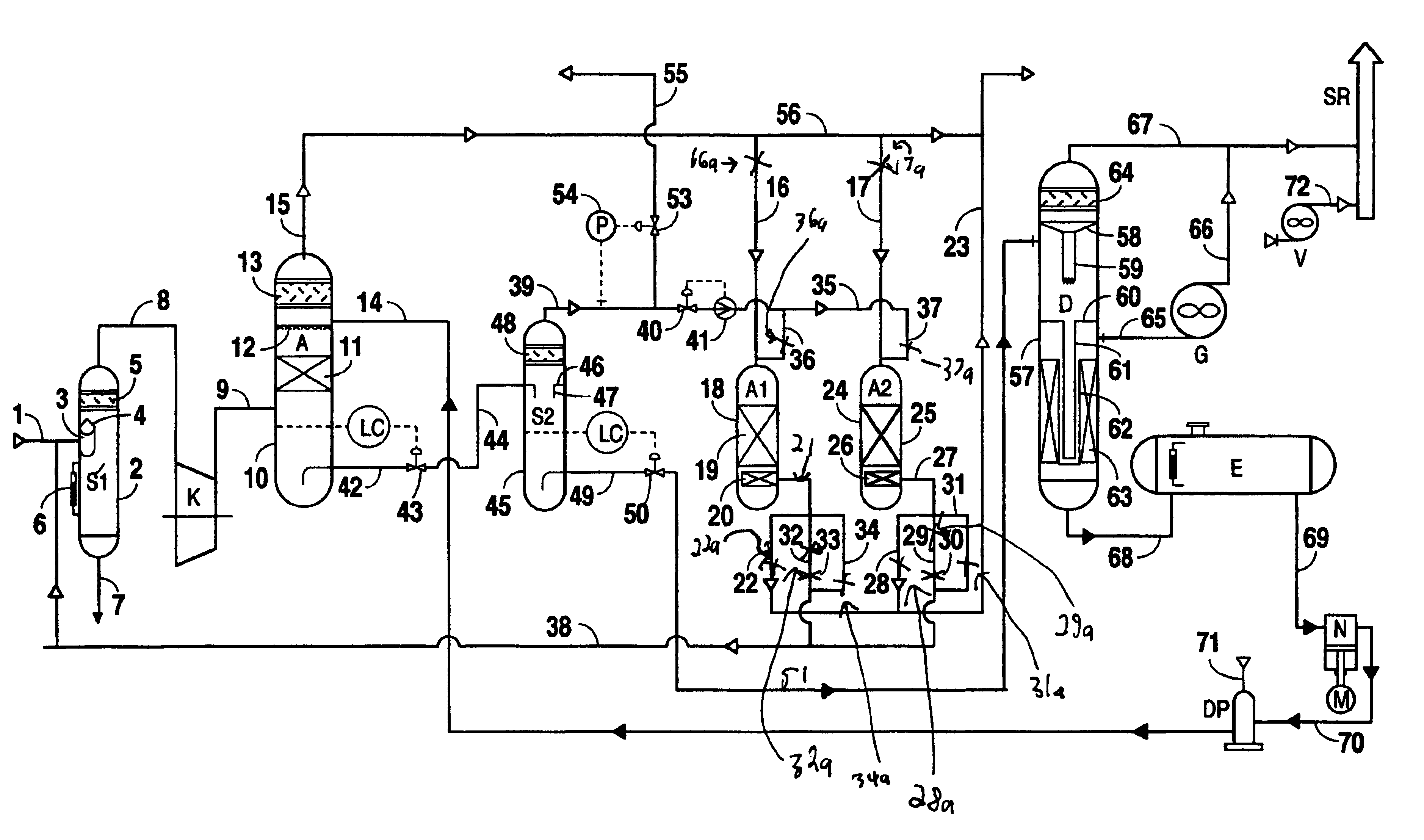
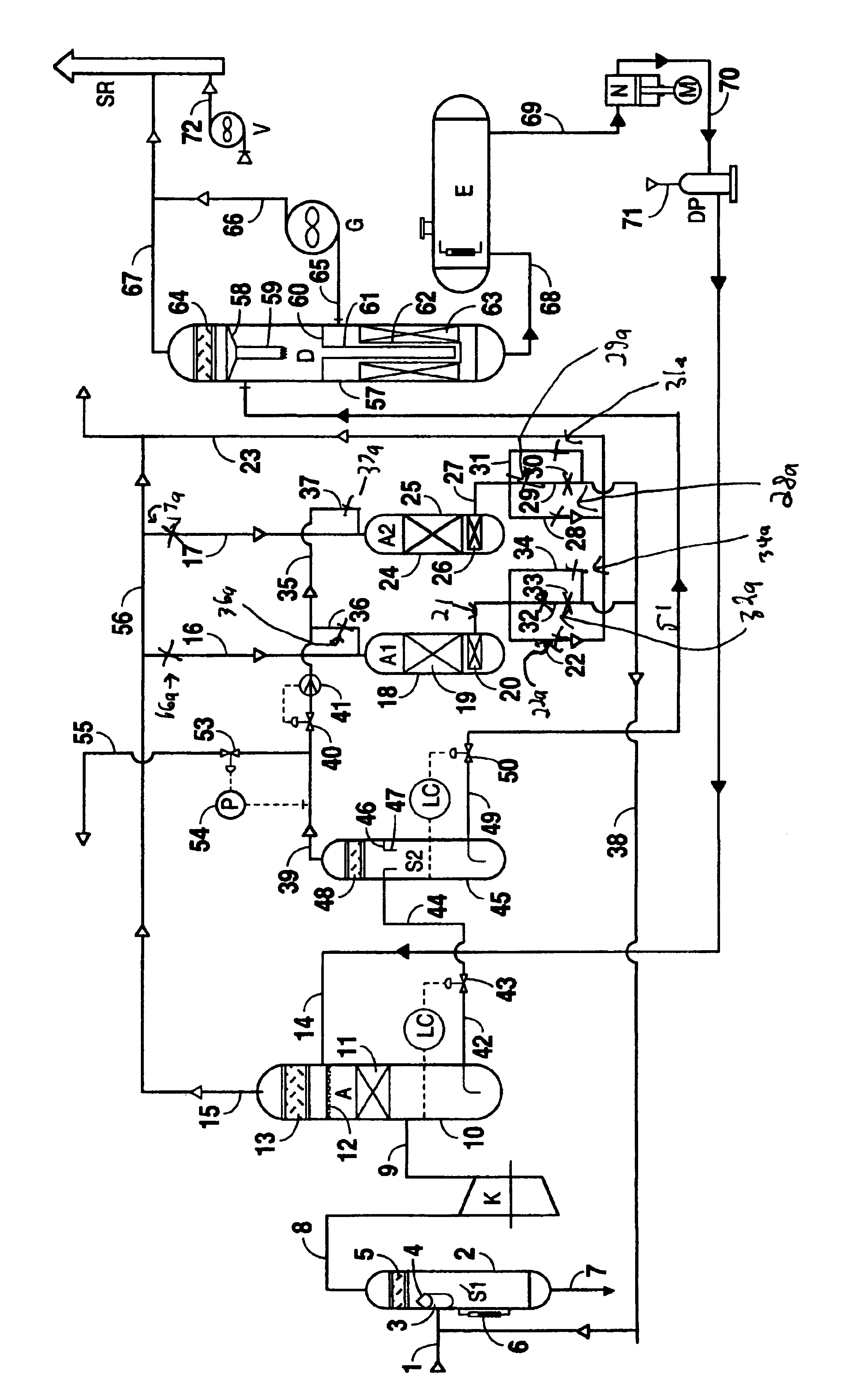
[0039]The purification process of the invention is designed to work with excessive landfill methane gas output compared to its extraction from a landfill. Vacuum is not used in the supplying pipeline because any entry of air should be avoided. Landfill methane gas output from landfills may vary considerably depending on season, day and night, rains, cold etc.

[0040]On closed landfills the landfill methane gas may flow from wells to a collector at the quantity of as much as 300 m3 / hour (10595 feet3 / hour) and more, depending on the volume of a landfill, year of usage, time of the year, day or night, weather conditions and other. The gas in the collectors is usually burned by flaring.

[0041]As shown in FIG. 1, the gas flows from a collector through a pipeline 1 to a separator S1. The separator S1 comprises a cylindrical body 2 with elliptic end caps. The separator S1 includes a shaped partition 3 with a lid 4, and a filter element 5 inside the separator.

[0042]The gas flowing in the pipel...


PUM

PropertyMeasurementUnit
pressureaaaaaaaaaa
temperaturesaaaaaaaaaa
pressureaaaaaaaaaa

Abstract

A process for concentrating and recovering methane and carbon dioxide from landfill gas includes absorption of commonly occurring pollutants using a carbon dioxide absorbent which itself may be in situ recoverable constituent. Separated methane is concentrated into a high heating value fuel, and a carbon dioxide product may also be recovered. Process streams may be used to provide fuel for compression and refrigeration and to regenerate carbon dioxide absorbent.

Description

BACKGROUND OF THE INVENTION[0001]1. Field of the Invention[0002]This invention generally relates to the separation and recovery of methane and carbon dioxide from landfill gas. Process streams provide fuel for compression and refrigeration and / or to regenerate absorbent added to the process for further separation of methane and carbon dioxide.[0003]2. Description of the Related Art[0004]This invention generally relates to the separation and recovery of methane and carbon dioxide from landfill gas. More particularly, the invention provides an improved process for concentrating and removing commonly occurring pollutants from landfill gas using a carbon dioxide absorbent which itself may be an in situ recoverable constituent. The separated methane may be used to provide a source of natural gas, and carbon dioxide product may also be recovered from the landfill gas. Process streams may be used to provide the recovery system and / or to regenerate absorbent used in the process for further ...

Claims


Application Information

Patent Timeline
Patent Type & Authority Patents(United States)
IPC IPC(8): B01D53/26B01D53/14C01B31/20C01B31/00B09B1/00C01B32/50C10L3/08
CPCB01D53/1475B01D53/261B09B1/00C01B31/20C10L3/08B01D2257/504Y02C10/04Y02C10/06Y02C10/08Y02E50/346B01D2258/05C01B32/50Y02E50/30Y02W30/30Y02P20/151Y02C20/40
Inventor KRUSHNEVYCH, TADEUSHPIATNYCHKO, OLEXANDER
Owner CONSORTIUM SERVICES MANAGEMENT GROU
Why Eureka
Try Eureka