Electric apparatus having a stator with insulated end laminations within the central opening of end plates

a technology of electric apparatus and stator, which is applied in the direction of windings, dynamo-electric components, and magnetic circuit shapes/forms/construction, etc., can solve the problems of increased motor cost, increased process cost, and inability to meet the requirements of the electric motor, so as to prevent the likelihood of a short circuit and improve the manufacturing of the electric motor. , the effect of rapid and cost-effective solution

Inactive Publication Date: 2005-08-16
BALDOR ELECTRIC COMPANY
View PDF15 Cites 18 Cited by
  • Summary
  • Abstract
  • Description
  • Claims
  • Application Information

AI Technical Summary

Benefits of technology

[0010]The inventive technique offers distinct advantages over existing techniques. For example, the technique enables automated machine winding processes, such as inserting the coils, lacing the coils, and forming the coils. The machine winding processes offer a rapid and cost-effective solution for improved manufacturing of the electric motor. Also, the technique provides for extra insulation between the coils in motor and the end plate or laminations. The technique provides a physical insulating barrier between the coils and other conductive components, which prevents the likelihood of a short circuit occurring. Moreover, the technique provides for additional support of the insulating material, such as slot liners, by providing support to those materials during the manufacturing processes. By supporting the insulating materials, the damage, such as shredding or tearing, is reduced and short circuits are prevented.

Problems solved by technology

While conventional motor manufacturing equipment and methods have been generally satisfactory in many applications, they are not without drawbacks.
This type of process is more expensive because it requires a larger labor force to complete the task, which results in an increase in the cost of the motors.
Furthermore, conventional motor manufacturing components for square motors have additional drawbacks related to the methods for assembling and winding the stator for the square frame.
The portion of the endplate that extends beyond the slots hinders automated winding processes for the motor.
Thus, the motor is typically hand wound, due to the over-extending end plate.
Moreover, conventional techniques for manufacturing a motor have additional drawbacks with regard to the winding process.
However, the slot liners may be damaged during the winding process.
This additional tool is undesirable and increases the time to manufacture and cost associated with manufacturing the motor.

Method used


Image

  • Electric apparatus having a stator with insulated end laminations within the central opening of end plates
  • Electric apparatus having a stator with insulated end laminations within the central opening of end plates
  • Electric apparatus having a stator with insulated end laminations within the central opening of end plates

Examples


Embodiment Construction

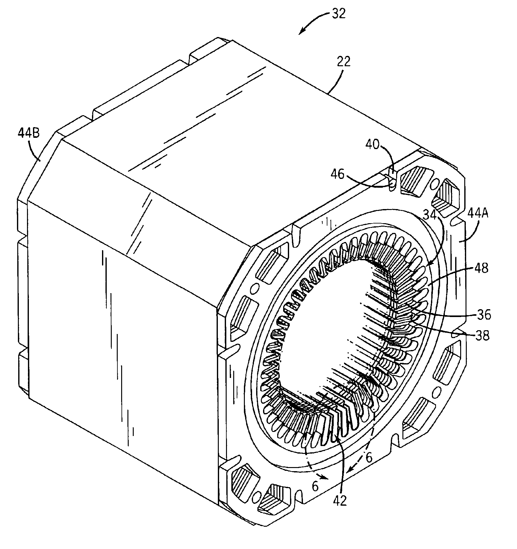
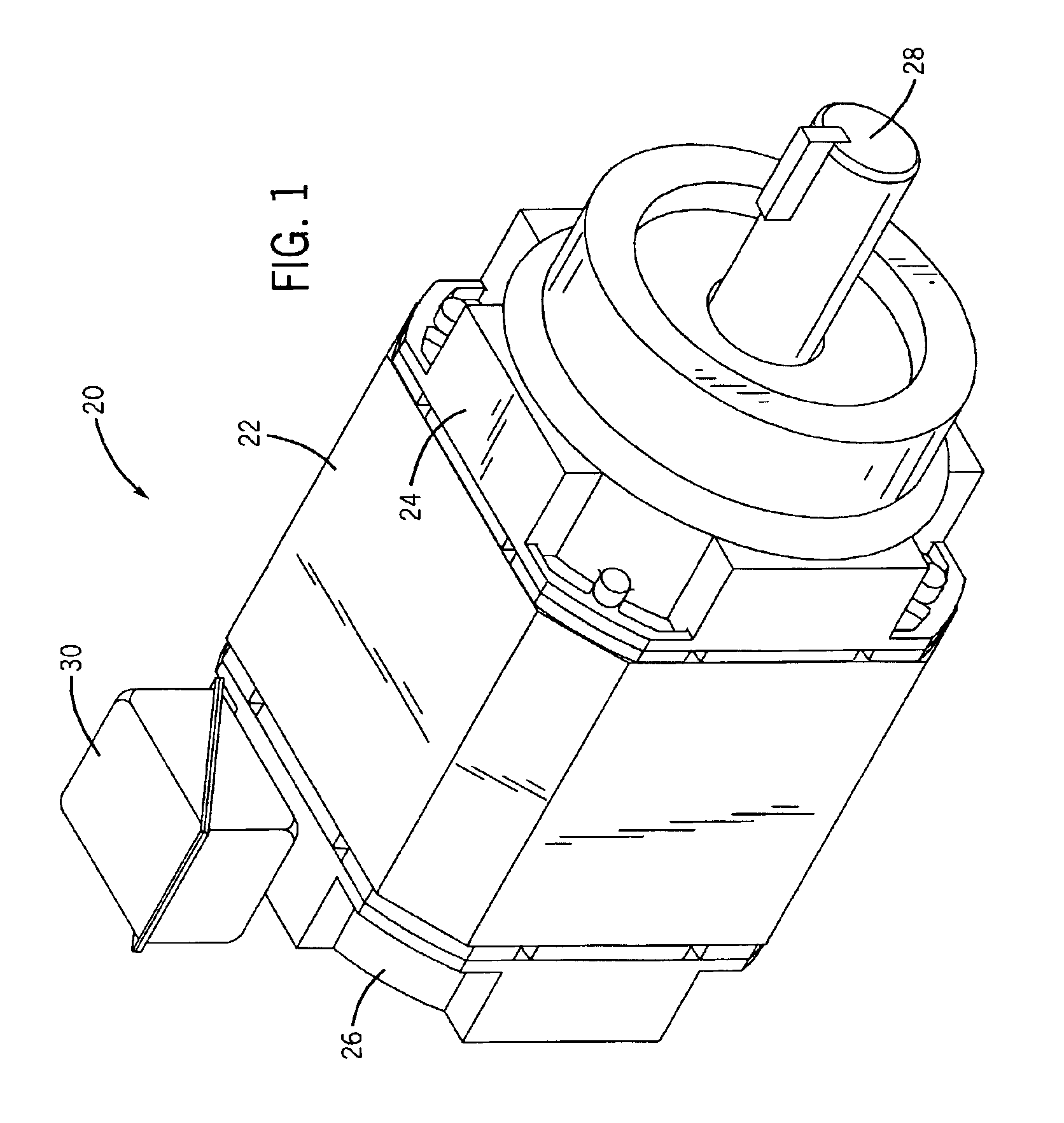
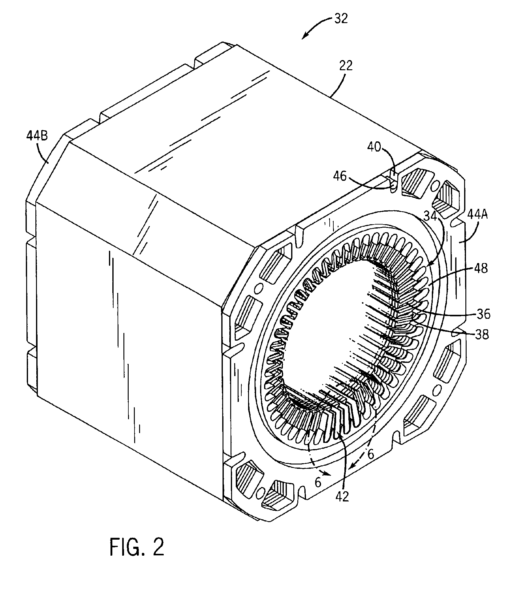
[0021]Turning now to the drawings, and referring first to FIG. 1, an electric motor is shown and designated generally by the reference numeral 20. In the embodiment illustrated in FIG. 1, motor 20 is an induction motor housed in a conventional NEMA enclosure. Accordingly, motor 20 includes a frame 22 open at front and rear ends and capped by a front end cap 24 and a rear end cap 26. The frame 22, front end cap 24, and rear end cap 26 form a protective shell, or housing, for a stator and a rotor. Stator windings are electrically interconnected to form groups, and the groups are, in turn, interconnected in a manner generally known in the art. The windings are further coupled to terminal leads (not shown). The terminal leads are used to electrically connect the stator windings to an external power cable (not shown) coupled to a source of electrical power. Energizing the stator windings produces a magnetic field that induces rotation of the rotor and a rotary shaft 28. The electrical co...


PUM

PropertyMeasurementUnit
widthaaaaaaaaaa
widthaaaaaaaaaa
widthaaaaaaaaaa

Abstract

A technique is provided for manufacturing a stator of an electrical machine, such as a motor. The stator is formed by using thin end plates or laminations that are attached to each other by rods around a group of laminations. The end plates maintain pressure on the laminations. Within the laminations, slots extend thru the length of the stator. A slot liner is placed within each slot as an insulating layer between coils and the laminations. Furthermore, an insulating end piece or lamination is positioned within each end plate and adjacent to the laminations to provide support to the slot liners that extend beyond the laminations. The insulating end lamination supports the slot liners during the winding processes to prevent the slot liners from damage. In addition to providing support, the insulating end lamination is able to provide extra insulation between the coils, laminations, and the end plate. Moreover, by having thin end plates, the motor may be wound by automated processes to reduce the cost of manufacture.

Description

BACKGROUND OF THE INVENTION[0001]The present invention relates generally to the field of electric motors and methods and apparatus for manufacturing electric motors. More particularly, the invention relates to a novel technique for manufacturing motors that may be machine wound.[0002]Electric motors of various types are omnipresent in industrial, commercial and consumer settings. In industry, such motors are employed to power all types of rotating machinery, such as pumps, conveyors, compressors, fans and so forth, to mention only a few. Conventional alternating current electric motors may be constructed for single or multiple phase operation, and are typically specifically designed to operate at predetermined synchronous speeds, such as 3600 rpm, 1800 rpm, 1200 rpm and so on. Such motors generally include a stator, comprising a multiplicity of coils, surrounding a rotor, which is supported by bearings for rotation in the motor frame. In the case of AC motors, alternating current po...

Claims


Application Information

Patent Timeline
Patent Type & Authority Patents(United States)
IPC IPC(8): H02K3/34H02K1/16H02K3/32H02K3/50
CPCH02K1/16H02K3/345Y10T29/49009H02K3/50
Inventor GRANT, BARRON D.CUFR, THOMAS S.EVON, THOMAS S.LAMBERT, JR., GRAYSON W.
Owner BALDOR ELECTRIC COMPANY
Why Eureka
Try Eureka