Device and method for transmitting data between a sensor and an analyser unit

a technology of data transmission and analyser, which is applied in the direction of transmission systems, engine lubrication, liquid/fluent solid measurement, etc., can solve the problems of inability to adjust, for example by means of the torsion of a potentiometer or the installation of an additional resistor, and no clu

Inactive Publication Date: 2005-08-16
EHNDRESS KHAUZER GMBKH KO KG
View PDF6 Cites 6 Cited by
  • Summary
  • Abstract
  • Description
  • Claims
  • Application Information

AI Technical Summary

Benefits of technology

[0008]The object of the invention is to provide a device and a method which make it possible to test and / or to adjust and / or to operate a sensor, which is part of the process, from the outside.

Problems solved by technology

However, the laid-open publication does not contain any clue regarding a bidirectional data exchange between the probe and the remotely located evaluating unit.
Since sensors are customarily encapsulated following mounting, an adjustment, for example by means of the torsion of a potentiometer or the installation of an additional resistor, is no longer possible.

Method used


Image

  • Device and method for transmitting data between a sensor and an analyser unit
  • Device and method for transmitting data between a sensor and an analyser unit
  • Device and method for transmitting data between a sensor and an analyser unit

Examples


Embodiment Construction

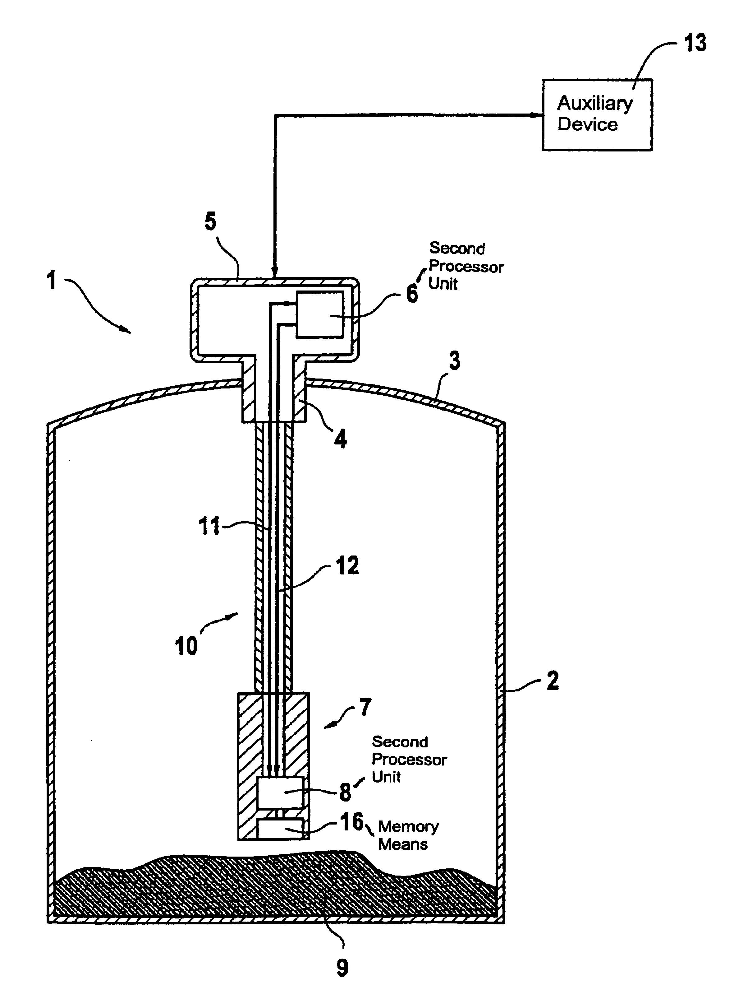
[0029]FIG. 1 shows a schematic representation of an embodiment of the device 1 of the invention. In the case illustrated, the device 1 of the invention is intended to determine the fill level limit of a filler material 9 in the container 2. The device 1 is put together from a sensor 7, which is in the container 2, an evaluating unit 5, which is mounted outside of the container in an opening 4 in the cover 3 of the container 2, and a connecting means 10, for example a cable or a rope, which connects the sensor 7 with the evaluating unit 5.

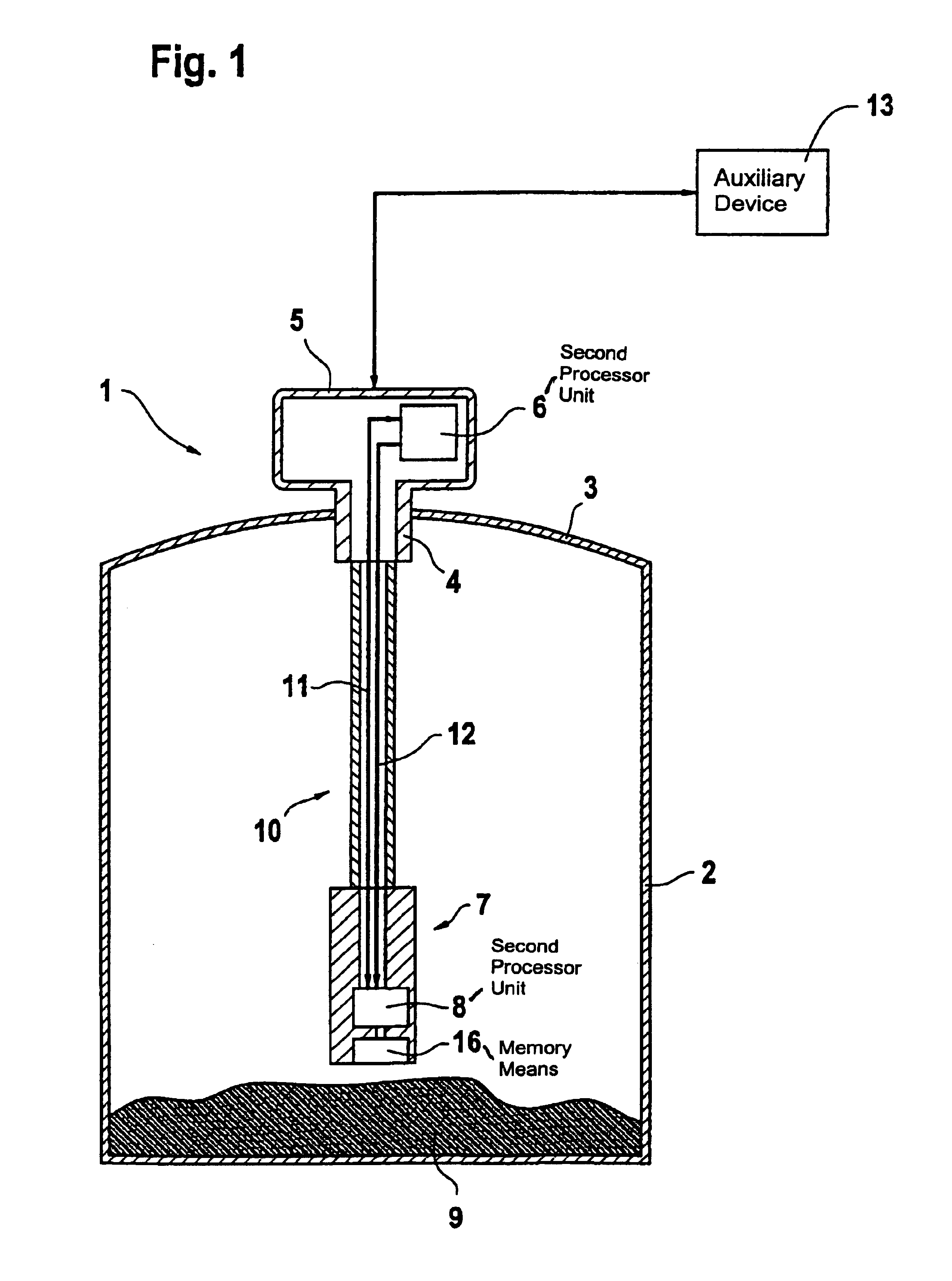
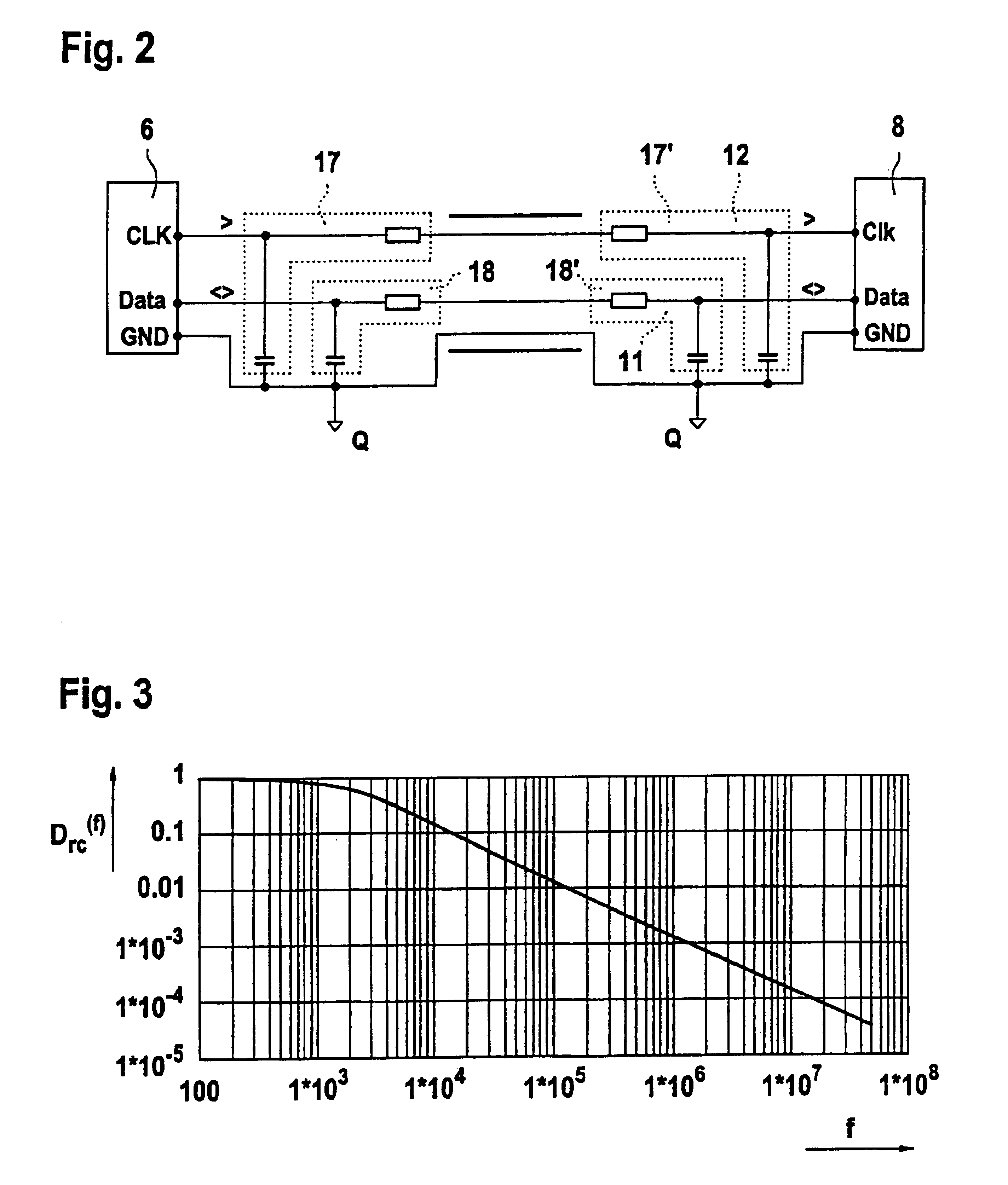
[0030]A first processor unit 6 is assigned to the evaluating unit 5, and a second processor unit 8 to the sensor 7. The processor unit 6 assigned to the evaluating unit 5 preferably is a master processor, and the processor unit 8 assigned to the sensor 7 is a slave processor. Both processor units 6, 8 communicate with each other via data lines 11, 12, wherein the data line 11 is a unidirectional data line, over which the master processor 6 provides ...


PUM

PropertyMeasurementUnit
frequencyaaaaaaaaaa
electric currentaaaaaaaaaa
time constantsaaaaaaaaaa

Abstract

A device for transmitting data between a sensor, in particular a capacitive level sensor, and an analyser unit, whereby the sensor and the analyser unit are physically separate from each other and a method for operating said device. The device and method permit the testing and/or adjusting and/or operation of a sensor, which is active. A first processor unit is dedicated to the sensor and a second processor unit is dedicated to the evaluating unit. Connecting lines are provided, by means of which both processor units exchange bi-directional data.

Description

FIELD OF THE INVENTION[0001]The invention relates to a device for transmitting data between a sensor, in particular a capacitive fill-level sensor or a pressure sensor, and an evaluating unit, wherein the sensor and the evaluating unit are spatially separated. Moreover, the invention relates to a method for adjusting, testing and operating the device in accordance with the invention.BACKGROUND OF THE INVENTION[0002]Although reference will always be made to a capacitive fill-level sensor in what follows, the invention can basically be applied to any type of measuring device in which the sensor and the evaluating unit have a defined spatial distance from each other. Thus, the device in accordance with the invention, or the method in accordance with the invention, can also be employed in connection with a pressure sensor.[0003]A capacitive fill-level probe is known from DE 195 36 199 C2, which is mounted at the level of the fill level to be monitored. Such probes are also called thresh...

Claims


Application Information

Patent Timeline
Patent Type & Authority Patents(United States)
IPC IPC(8): G08C19/02G01L19/08G01F23/00G08C19/00
CPCG08C19/02
Inventor FLORENZ, HANS-JORGWERNET, ARMIN
Owner EHNDRESS KHAUZER GMBKH KO KG
Why Eureka
Try Eureka