Multi-beam light scanning optical system and image forming apparatus using same

a light scanning optical system and multi-beam technology, applied in the direction of inking apparatus, optical elements, instruments, etc., can solve the problems of insufficient confinement of the light beam in the main scan direction on the polygonal mirror surface, prevent image quality or the like, and achieve satisfactory printing precision and image quality. , the effect of preventing the deterioration of printing precision and image quality

Inactive Publication Date: 2005-08-16
CANON KK
View PDF12 Cites 6 Cited by
  • Summary
  • Abstract
  • Description
  • Claims
  • Application Information

AI Technical Summary

Benefits of technology

[0012]The defocusing in the main scan direction is caused by various factors; for example, imaging performance of the optical parts, positional accuracy between the parts or the like, which cannot be completely removed. Accordingly, it is very difficult to prevent the deteriorations of the printing precision, the image quality or the like attributable to the deviation of the imaging ...

Problems solved by technology

However, the method described above is not sufficient to confine the expans...

Method used


Image

  • Multi-beam light scanning optical system and image forming apparatus using same
  • Multi-beam light scanning optical system and image forming apparatus using same
  • Multi-beam light scanning optical system and image forming apparatus using same

Examples


embodiment 1

(Embodiment 1)

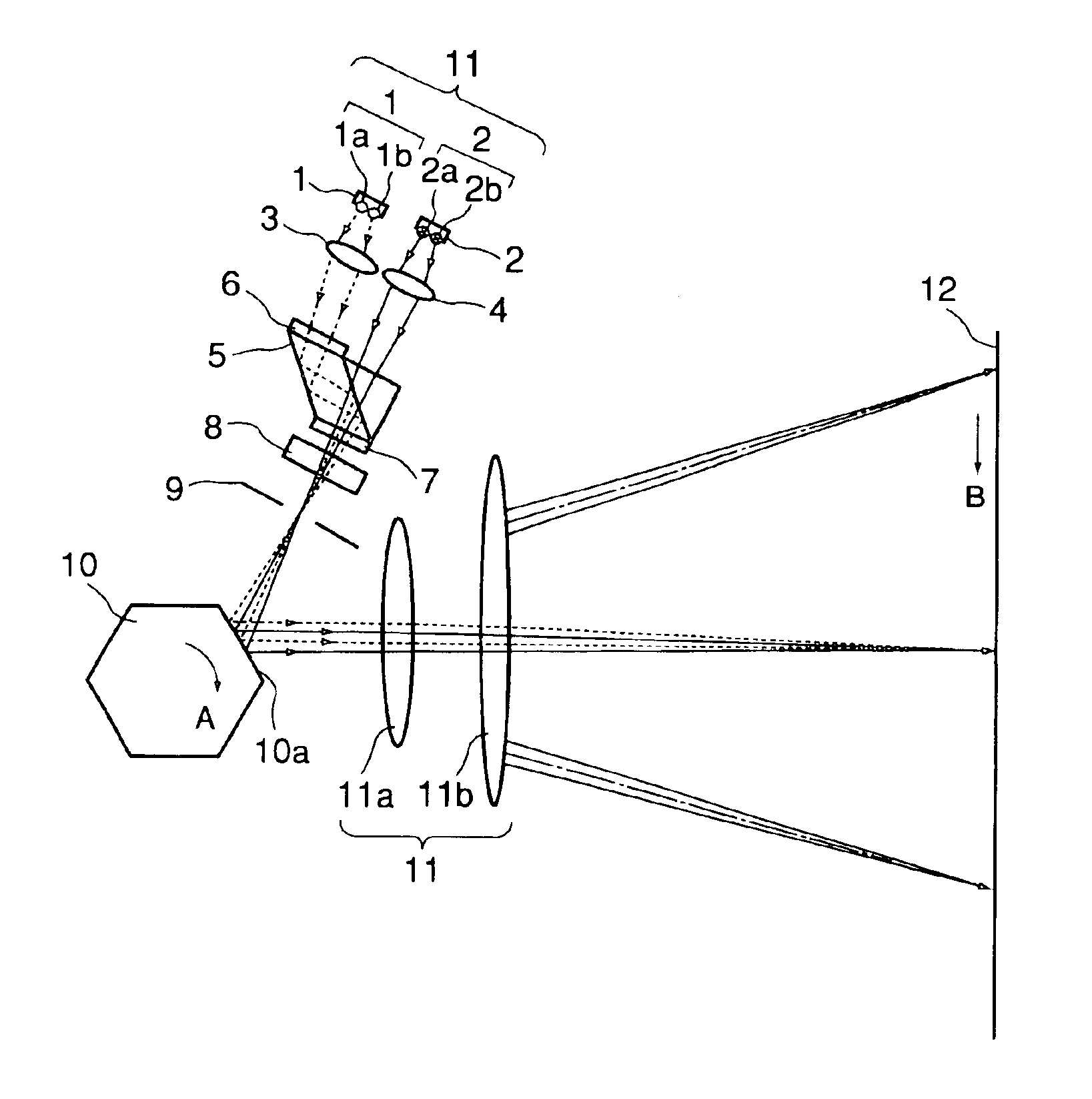
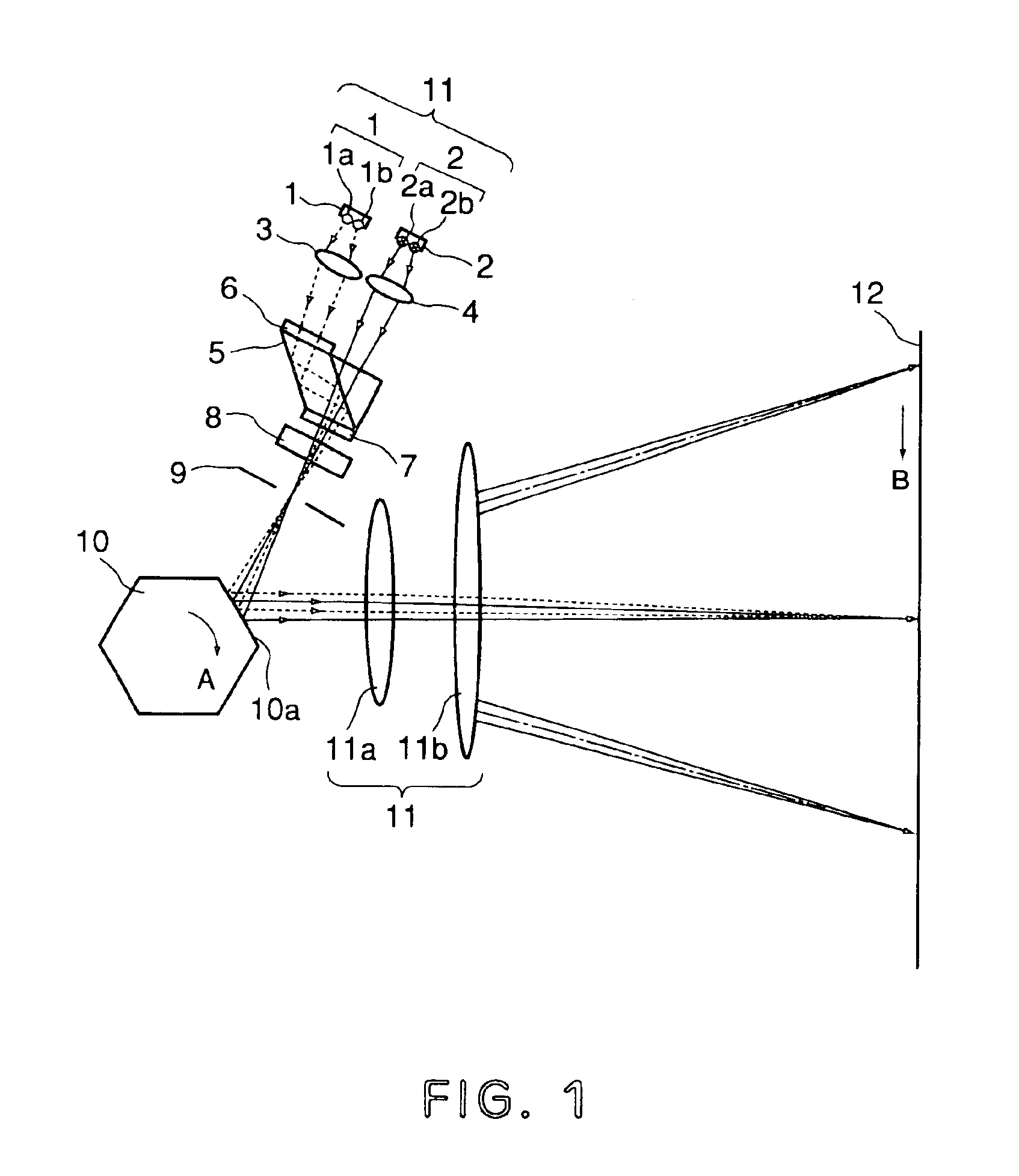
[0071]FIG. 1 is a sectional view (main-scanning section view) of a major part of a multi-beam scanning optical system according to Embodiment 1 of the present invention.

[0072]In this specification, a main-scanning section is a view of a plane including an optical axis of an imaging optical system and a light beam (ray) deflected by the light deflector, and a sub-scan section is a view of a plane including an optical axis of the imaging optical system and perpendicular to the main-scanning section.

[0073]In this Figure, designated by 11 is a light source apparatus comprising first and second light source means 1, 2; the first light source means 1 includes two emitting points 1a, 1b, and the second light source means 2 includes two emitting points 2a, 2b, too.

[0074]3, 4 designated by reference numerals 3, 4 are coupling lenses (collimator lenses) disposed corresponding to the first and second light source means 1, 2 to convert the four beams emitted from the first and sec...

embodiment 2

(Embodiment 2)

[0101]FIG. 3 is a sectional view (main-scanning section view) of a major part in the main scan direction of a multi-beam light scanning optical system according to Embodiment 2. In this Figure, the same reference numerals as in FIG. 1 are assigned to the elements having the corresponding functions.

[0102]This embodiment is different from the Embodiment 1 in that light source apparatus 31 comprises a first light source means 21 having one emitting point 21a and a second light source means 22 having two emitting points 22a, 22b. The other structures and optical functions are substantially the same as with Embodiment 1, and the similar effect are provided.

[0103]In the Figure, designated by 31 is a light source apparatus which comprises first light source means 21 having one emitting point 21a and second light source means 22 having two emitting points 22a, 22b.

[0104]The beam synthesizing means is constructed such that principal ray of the light beam emitted from the first...

embodiment 3

(Embodiment 3)

[0106]FIG. 4 is a sectional view (main-scanning section view) of a major part in the main scan direction of a multi-beam light scanning optical system according to Embodiment 2. In this Figure, the same reference numerals as in FIG. 1 are assigned to the elements having the corresponding functions.

[0107]This embodiment is different from Embodiment 1 in that multi-beam light scanning optical system is constructed by an over-field scanning optical system. The other structures and optical functions are substantially the same as with Embodiment 1, and the similar effect are provided.

[0108]Four light beams are incident on the deflection surface 20a of the light deflector 20 having 12 surfaces, astride a plurality of deflection surfaces in the main-scanning section (the light beam has a width larger than the width of the deflection surface 20a measured in the main scan direction), and therefore, the width of the deflection surface 20a In the main scan direction functions as ...


PUM


Abstract

A multi-beam light scanning optical system includes n (n≧2) light source means having m (m≧2) light emitting points; beam synthesizing means for synthesizing n×m light beams emitted by the light source means; deflecting means for deflecting n×m light beams from the beam synthesizing means; an imaging optical system for imaging the n×m light beams from the deflecting means on a surface to be scanned, wherein the surface to be scanned is scanned in a main scan direction with n×m light beams by a deflection scanning operation of the deflecting means; an aperture stop provided between the beam synthesizing means and the deflecting means, wherein principal rays of the n×m light beams are intersected at a position of the aperture stop, and the light beams which are adjacent to each other in a sub-scan direction on the surface to be scanned are the beams emitted from different ones of the light source means.

Description

FIELD OF THE INVENTION AND RELATED ART[0001]The present invention relates to a multi-beam light scanning optical system and an image forming apparatus using the same, more particularly to a multi-beam light scanning optical system capable of high speed light scanning of a surface using a plurality of light source means, particularly suitable for an image forming apparatus such as a laser beam printer, a digital copying machine, a multi-function printer or the like.[0002]A light scanning optical system is widely used as a writing optical system for a laser beam printer, a digital copying machine, a multi-function printer or the like, and there is a demand for high image quality and high speed scan in order to raise the scanning speed, it is considered to increase the number of surfaces of the polygonal mirror (light deflector) or to raise the rotational frequency of the polygonal mirror to 2 times, 3 times or even higher, but such a simple change of the optical factors imparts too hi...

Claims


Application Information

Patent Timeline
IPC IPC(8): B41J2/435B41J2/47G02B26/12H04N1/113G02B6/42B41J2/44G02B26/10
CPCB41J2/473G02B26/123H04N1/113G02B6/4249G02B26/10
Inventor YAMAWAKI, TAKESHI
Owner CANON KK
Why Eureka
Try Eureka