Array transducer-based side-scanning photoacoustic-ultrasonic endoscope

a photoacoustic-ultrasonic, side scanning technology, applied in ultrasonic/sonic/infrasonic image/data processing, catheters, applications, etc., can solve the problems of low cost of implementing the related instruments, difficult to reduce the size of the related endoscopic probe, and inability to meet the requirements of both commercially successful or clinically applicable pae systems. to achieve the effect of imaging performan

Active Publication Date: 2021-02-02
UNIST ULSAN NAT INST OF SCI & TECH
View PDF30 Cites 3 Cited by
  • Summary
  • Abstract
  • Description
  • Claims
  • Application Information

AI Technical Summary

Benefits of technology

[0049]As mentioned above, the present disclosure relates to an array-transducer-based side-scanning PAE probe and system, and a main objective of the present disclosure is to provide a more advanced endoscopic structure that does not suffer from the mismatch issue between an optical illumination area (IA) and an ultrasonic scan area (SA) that exists in the prior inventions. More specifically, the present disclosure aims to work out a novel PAE probe structure with an imaging performance that is significantly better than that of existing PAE probes, especially in terms of imaging depth, by using an array transducer as a signal detector in order to utilize the PAE probe to diagnose digestive diseases or heart diseases via a GI tract introduction.
[0052]In the general video endoscopes and EUS probes utilized for clinical GI endoscopy, the diameter of the hose portion inserted into the human body typically ranges from ˜1 cm to ˜1.3 cm in order for the hose portion to be inserted into a digestive tract, such as the esophagus or the large intestine, without much difficulty. However, in order to add a probe steering function to those hose portions, such as the probe angulation capability, it is necessary to install a related unit at a point that is as close as possible to the distal end of a hose. This means that better probe steering performance can be achieved as the total length of a scanning head section, which is typically inflexible and in which an array transducer is installed, decreases.
[0056]If the discussed PAE probe must also have large-depth imaging performance, like existing array transducer-based EUS probes, the aforementioned size issue makes the situation even more difficult. This is because, in order to achieve large-depth imaging, a sufficient amount of light energy has to be delivered to an object to be examined, but the total area available for light illumination, which can be simply calculated by subtracting the area needed for the array transducer from the entire area (i.e., ˜1.3 cm×3 cm) formed on the outer surface of the scanning head section, is significantly reduced.
[0062]Of course, the above-described prior inventions may be able to further improve the imaging depth by simply increasing the amount of laser energy emitted through optical fibers (for example, as reported in Prior Document 15). However, in this case, those PAE systems may violate the safety limit regulations of the American National Standards Institute (ANSI) (see Prior Document 16), which state that the flow of light energy per unit area (1 cm2) should not exceed 20 mJ, regardless of the flow direction anywhere on a surface of biological tissue during laser beam irradiation to the biological tissue.

Problems solved by technology

(1997), as described in Prior Document 8, in which the imaging probe was referred to as an “optoacoustic endoscope”, a number of PAE probes have been developed to address technical requirements, such as “probe miniaturization” and “specifying a device configuration or operation principle for endoscopy.” However, no commercially successful or clinically applicable PAE system has yet been developed that satisfies both of these technical requirements due to many underlying technical challenges.
The most well-known and difficult challenge is that, in order to successfully create a working PAE probe, all the optical and acoustical elements should be effectively integrated and arranged in a small and restricted space; an adequate scanning mechanism, through which a tomographic image can be produced, should also be developed and integrated into the device.
Moreover, the costs for implementing the related instruments are relatively low.
However, the main drawback of the mechanical scanning mechanism is that, since a single-element ultrasonic transducer that can receive the signals that are bounced back only from the aiming direction of the transducer surface is mounted on the scanning tip of an endoscopic probe, in order to obtain a 2D image or a 3D image, a series of processes that emit a laser pulse, and then detect the generated photoacoustic waves, should be repeatedly performed by changing the physical position or the aiming direction of the ultrasonic transducer (e.g., rotational scanning in general).
First, its major drawback is that it is relatively more difficult to reduce the size of the related endoscopic probe than the size of the mechanical scanning mechanism because it employs multiple transducer elements to detect ultrasound waves.
Thus, problems, such as crosstalk or signal interference between channels, may occur and the cost of implementing the system may also be high.
However, Prior Document 9 only mentioned the possibility of applying this array sensor to PAE or intravascular imaging; it does not disclose any detailed shape or structure of a PAE probe or the associated implementation methods.
However, the endoscopic system as is may not be applicable to a clinical endoscopic procedure because its probe is still too big (9 cm in length and 3 cm in diameter), and the glass material utilized for the probe encapsulation is not suitable for actual clinical use in terms of safety.
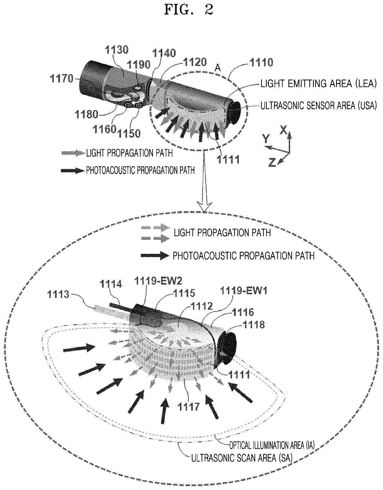
Moreover, the endoscopic system of Prior Document 10 has a drawback in that a light emitting area (LEA) and an ultrasonic sensor area (USA) are spaced apart from each other (the problem caused by such an arrangement will be explained later).
However, the proposed structure has a disadvantage in that, since a limited number of optical fibers are simply added to the outer surface of an existing array transducer-based IVUS catheter, the intensity of light illumination may not be uniform over the 360° scan area, and the probe's flexibility may not be good enough.
However, in this case, the probe flexibility may be seriously decreased in proportion to the total number of optical fibers that are used.
However, the endoscopic probe presented in Prior Document 13 has a disadvantage in that, since the probe has a structure that obtains a photoacoustic signal by using only an 8-element-based array transducer, which is placed facing the distal end of the probe, a parabolic mirror, which has a 45°-tilted reflection surface and faces that array transducer, has to mechanically rotate in order to obtain a photoacoustic image over a desired scan range.
Thus, the suggested scanning mechanism may not be a desirable direction for actual clinical use because the main purpose of using this type of array transducer is to avoid any mechanically moving component inside an endoscopic probe.
However, as mentioned above (Prior Document 13), the core benefit of employing an array transducer was not fully utilized, and the mismatch issue between an LEA and a USA still exists in this endoscopic system.
However, in any case, the endoscopic structures presented in Prior Document 15 have the limitation that the LEA of an endoscopic probe is limited to the surrounding area of an array transducer or several spots that are discontinuously distributed around a linear array transducer.
This limitation was probably caused because the authors of Prior Document 15 only focused on a PAE probe embodiment by using an existing commercial ultrasonic array transducer, rather than focusing on working out an ideal probe structure that enables a uniform light illumination to an object to be examined over the entire area where the transducer elements are distributed.
This leads to the following problem: light energy is not uniformly delivered over the entire scan area (i.e., SA) of an array transducer during its scanning process, so a dead zone occurs in an acquired photoacoustic image.
However, if the size of a scanning head is reduced while maintaining this type of an arrangement structure, one serious effect is that the maximum imaging depth of the PAE probe may be greatly reduced because the total available space for the scan head still has to be divided into the two compartments, i.e., an LEA and a USA, as the arrangement structure is pre-assumed.
It is true that, in prior inventions, an LEA is limited only to specific positions so the total amount of light energy that is actually delivered to an object to be examined may be significantly limited.
Therefore, reducing the size of the probe may not be a desirable way to solve the aforementioned discrepancy issue.

Method used


Image

  • Array transducer-based side-scanning photoacoustic-ultrasonic endoscope
  • Array transducer-based side-scanning photoacoustic-ultrasonic endoscope
  • Array transducer-based side-scanning photoacoustic-ultrasonic endoscope

Examples


Embodiment Construction

[0085]The present disclosure may include various embodiments and modifications, and embodiments thereof will be illustrated in the drawings and will be described herein in detail. The advantages and features of the present disclosure and methods of achieving the advantages and features will be described more fully with reference to the accompanying drawings, in which embodiments are shown. The present disclosure may, however, be embodied in many different forms and should not be construed as being limited to the embodiments set forth herein.

[0086]Reference will now be made in detail to embodiments, examples of which are illustrated in the accompanying drawings. In the drawings, the same elements are denoted by the same reference numerals, and a repeated explanation thereof will not be given.

[0087]It will be understood that although the terms “first”, “second”, etc. may be used herein to describe various elements, these elements should not be limited by these terms. These elements ar...


PUM

PropertyMeasurementUnit
diametersaaaaaaaaaa
lengthaaaaaaaaaa
lengthaaaaaaaaaa

Abstract

A photoacoustic-ultrasonic (i.e. dual mode) endoscope includes: an optical fiber; a light diffuser configured to diffuse a laser beam delivered through the optical fiber to a target point of an object to be examined; and an array transducer through which the diffused laser beam passes and configured to generate ultrasonic waves or detect ultrasonic waves generated in the object to be examined.

Description

CROSS-REFERENCE TO RELATED APPLICATION[0001]This application claims the benefit of Korean Patent Application No. 10-2017-0020710, filed on Feb. 15, 2017, in the Korean Intellectual Property Office, the disclosure of which is incorporated herein in its entirety by reference.BACKGROUND1. Field[0002]One or more of the embodiments of the present disclosure relate to a medical tomographic endoscopic apparatus that has a probe that is long and slender, like the current endoscopic ultrasound (EUS) probes utilized in clinics, wherein the endoscopic apparatus is inserted into an object to be examined and provides a tomographic image of the interior thereof. The main objective of the present disclosure is to provide new system concepts and detailed probe structures to enable large-depth imaging that approaches the theoretical limit according to the imaging principle of photoacoustic tomography (PAT), wherein a restricted probe size (or optical illumination area) is also under a premise. Moreo...

Claims


Application Information

Patent Timeline
Patent Type & Authority Patents(United States)
IPC IPC(8): A61B8/00A61B5/00A61B8/12A61B8/08
CPCA61B8/4416A61B5/0062A61B5/0073A61B5/0084A61B5/0095A61B8/12A61B8/4483A61B8/483A61B8/5246A61B8/5269A61B8/4477A61B8/4494
Inventor YANG, JOON MOKIM, CHAE UN
Owner UNIST ULSAN NAT INST OF SCI & TECH
Why Eureka
Try Eureka