Back EMF voltage transducer/generator to convert mechanical energy to electrical energy for use in small disk drives

a technology of voltage transducer and generator, which is applied in the direction of record carrier contruction details, record information storage, instruments, etc., can solve the problems of not addressing the total amount of power, consuming a considerable amount of power on the disk drive of such systems, and consuming power

Inactive Publication Date: 2005-08-16
WESTERN DIGITAL TECH INC
View PDF10 Cites 55 Cited by
  • Summary
  • Abstract
  • Description
  • Claims
  • Application Information

AI Technical Summary

Benefits of technology

[0010]According to another embodiment thereof the present invention is a method of operating a disk drive, comprising drawing electrical energy from an energy storage device to process and execute commands for reading and writing to the disk; generating electrical energy by converting a motion of the disk drive into electrical energy, and charging the energy storage device using the generated electrical energy. The energy storage device may be a rechargeable battery and the drawing step may draw electrical energy from the rechargeable battery. The generating step may include providing a magnet and a conductive coil, and disposing the magnet and the coil such that the motion of the disk drive causes the magnet and the coil to move relative to one another to generate the electrical energy. Alternatively, the generating step may include providing a magnet and a conductive coil, and disposing the magnet and the coil such that the motion of the disk drive causes the magnet to move relative to the coil to generate the electrical energy. Alternatively still, the generating step may include providing a magnet and a conductive coil, and disposing the magnet and the coil such that the motion of the disk drive causes the coil to move relative to the magnet to generate the electrical energy. The generating step may include providing a generator enclosure; providing a conductive coil disposed within the generator enclosure, and providing a magnet, the coil and the magnet disposed such that the motion of the disk drive enclosure causes the coil and the magnet to move relative to one another to generate the electrical energy. The magnet-providing step may dispose the magnet within the generator enclosure such that the motion of the disk drive causes the magnet to oscillate relative to the coil. The magnet-providing step may also provide a spring within the generator enclosure, the spring being configured to enable the magnet to oscillate relative to the coil. The method may also include a step of sandwiching the magnet between a first spring and a second spring. The first and second spring may be configured such that when the motion of the disk drive causes one of the first and second springs to be in tension, the other of the first and second springs is in compression. The coil-providing step may dispose the coil within the generator enclosure such that the motion of the disk drive causes the coil to oscillate relative to the magnet. The magnet-providing step may also provide a spring within the generator enclosure. The spring may be configured to enable the coil to oscillate relative to the magnet. The method may also include a step of sandwiching the coil between a first spring and a second spring and the first and second spring may be configured such that when the motion of the disk drive causes one of the first and second springs to be in tension, the other of the first and second springs is in compression. The generator enclosure-providing step may provide a generator enclosure having a hollow cylindrical shape, for example. The magnet-providing step may provide a magnet having a disk shape or a right cylindrical shape, for example. The coil-providing step may provide a coil having a generally toroidal shape, for example. The method may further include a step of storing the generated electrical energy in a local storage device and the charging step may charge the rechargeable battery from the local storage device. The local storage device may include one or more capacitors, the capacitor(s) being selectively discharged to charge the rechargeable battery. The charging step may be carried out only when the disk drive is not drawing electrical energy from the energy storage means. The charging step may be carried out only after a predetermined time period has elapsed during which no commands for reading or writing to the disk have been processed, for example.

Problems solved by technology

The disk drives of such systems, however, consume a considerable amount of the power supplied by the energy storage device (typically, a rechargeable battery).
However, such approaches focus on power consumption and do not address the issue of the total amount of power available to be supplied to the mobile host device.
More particularly, these approaches do not operate to recharge the battery to actually increase the amount of power available to be supplied to the host device.

Method used


Image

  • Back EMF voltage transducer/generator to convert mechanical energy to electrical energy for use in small disk drives
  • Back EMF voltage transducer/generator to convert mechanical energy to electrical energy for use in small disk drives
  • Back EMF voltage transducer/generator to convert mechanical energy to electrical energy for use in small disk drives

Examples


Embodiment Construction

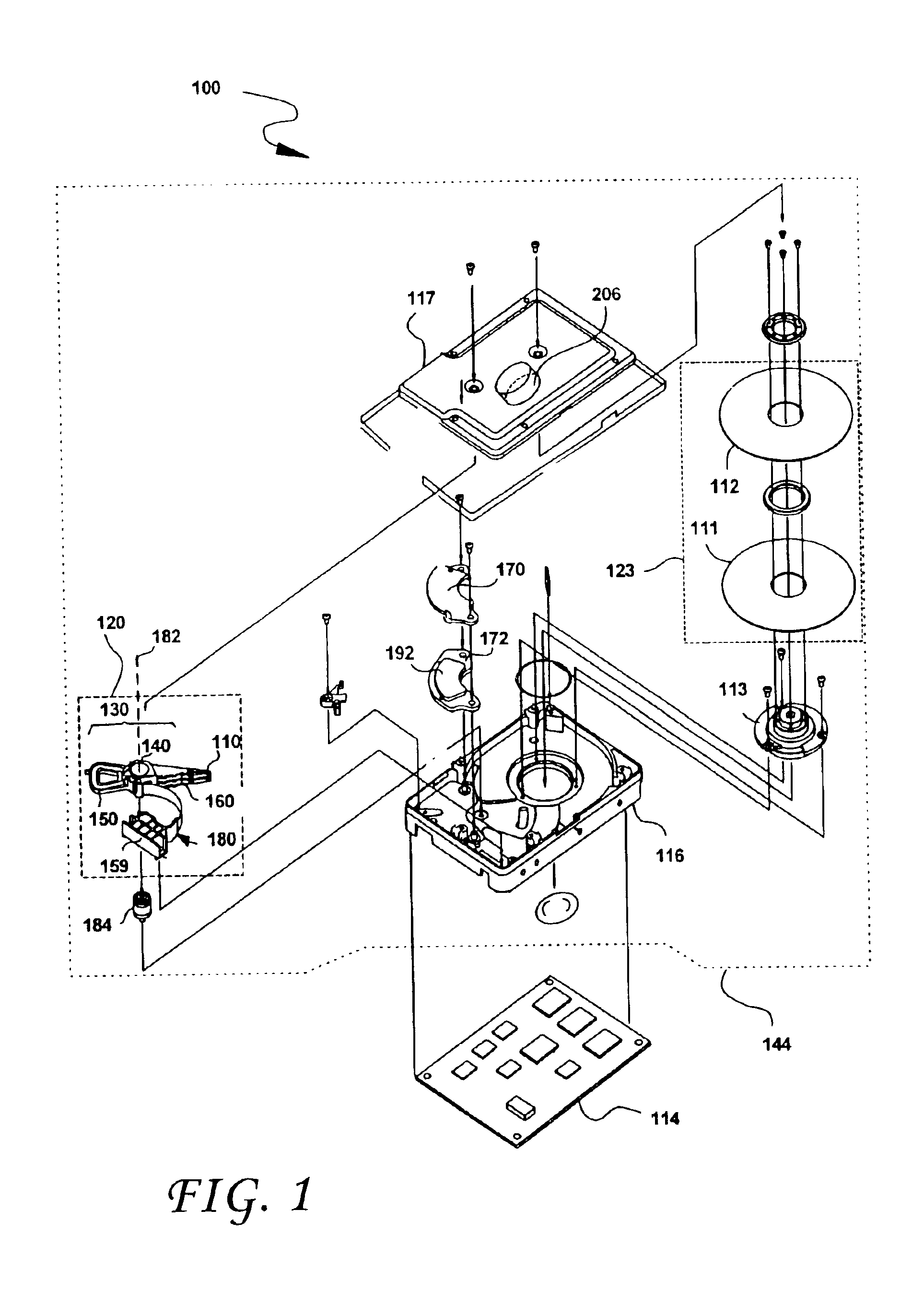
[0029]FIG. 1 shows the principal components of a magnetic disk drive 100 constructed in accordance with the present invention. With reference to FIG. 1, the disk drive 100 comprises a HDA 144 and a PCBA 114. The HDA 144 includes a disk drive enclosure comprising base 116 and a cover 117 attached to the base 116 that collectively house a disk stack 123 that includes one or a plurality of magnetic disks (of which only a first disk 111 and a second disk 112 are shown), a spindle motor 113 attached to the base 116 for rotating the disk stack 123, an HSA 120, and a pivot bearing cartridge 184 that rotatably supports the HSA 120 on the base 116. The spindle motor 113 rotates the disk stack 123 at a constant angular velocity. The HSA 120 comprises a swing-type or rotary actuator assembly 130, at least one HGA 110, and a flex circuit cable assembly 180. The rotary actuator assembly 130 includes a body portion 140, at least one actuator arm 160 cantilevered from the body portion 140, and a c...


PUM

PropertyMeasurementUnit
electrical energyaaaaaaaaaa
hollow cylindrical shapeaaaaaaaaaa
shapeaaaaaaaaaa

Abstract

A mobile host device configured to draw electrical energy from an energy storage device includes a disk drive. The disk drive includes a disk drive enclosure including a base, a spindle motor attached to the base, a disk positioned on the spindle motor, a generator and a charging circuit. The generator may be coupled to the disk drive enclosure and/or the mobile host device and generates electrical energy from the motion of the mobile host device and/or disk drive. The charging circuit is configured to charge the energy storage device using the electrical energy generated by the generator.

Description

BACKGROUND OF THE INVENTION[0001]1. Field of the Invention[0002]This invention relates to methods and devices for extending the charge of the energy storage device (e.g., battery) of mobile host devices that include a hard disk drive. More particularly, this invention relates to methods and devices for converting the mechanical energy of the movement of a disk drive containing mobile host device into electrical energy to charge the energy storage device of the host device.[0003]2. Description of the Prior Art and Related Information[0004]The growing popularity of portable electronic devices has coincided with significant advances in both the storage capacity of current hard disk drives as well as their miniaturization. Indeed, high capacity and inexpensive disk drives having a form factor of less than two inches are now widely available. The manufacturers of portable devices such as still and video cameras, portable digital assistants (PDAs), music players, telephones and mobile com...

Claims


Application Information

Patent Timeline
Patent Type & Authority Patents(United States)
IPC IPC(8): G11B33/12G11B19/00G11B25/04
CPCG11B19/00G11B25/043G11B33/122
Inventor CODILIAN, RAFFIOVEYSSI, KAMRAN
Owner WESTERN DIGITAL TECH INC
Why Eureka
Try Eureka