Router monitoring

Inactive Publication Date: 2005-08-16
IBM CORP
View PDF9 Cites 40 Cited by
  • Summary
  • Abstract
  • Description
  • Claims
  • Application Information

AI Technical Summary

Problems solved by technology

Running a dynamic routing protocol on every end-host may not be feasible for a number of reasons including: administrative overhead, processing overhead, security issues, or lack of a protocol implementation for some platforms.
Neighbor or router discovery protocols may require active participation by all hosts on a network, thus leading to large timer values (time to set up a link) to reduce protocol overhead in face of a large number of hosts.
This can result in significant delay in the detection of a lost (i.e., dead) neighbor, which may introduce unacceptably long “black hole” periods.
However, this creates a single point of failure.
Loss of the default router results in a catastrophic eve

Method used


Image

  • Router monitoring
  • Router monitoring
  • Router monitoring

Examples


Embodiment Construction

[0018]In the following description, numerous specific details are set forth to provide a thorough understanding of the present invention. However, it will be obvious to those skilled in the art that the present invention may be practiced without such specific details. In other instances, well-known circuits have been shown in block diagram form in order not to obscure the present invention in unnecessary detail For the most part, details concerning timing considerations and the like have been omitted in as much as such details are not necessary to obtain a complete understanding of the present invention and are within the skills of persons of ordinary skill in the relevant art.

[0019]Refer now to the drawings wherein depicted elements are not necessarily shown to scale and wherein like or similar elements are designated by the same reference numeral through the several views.

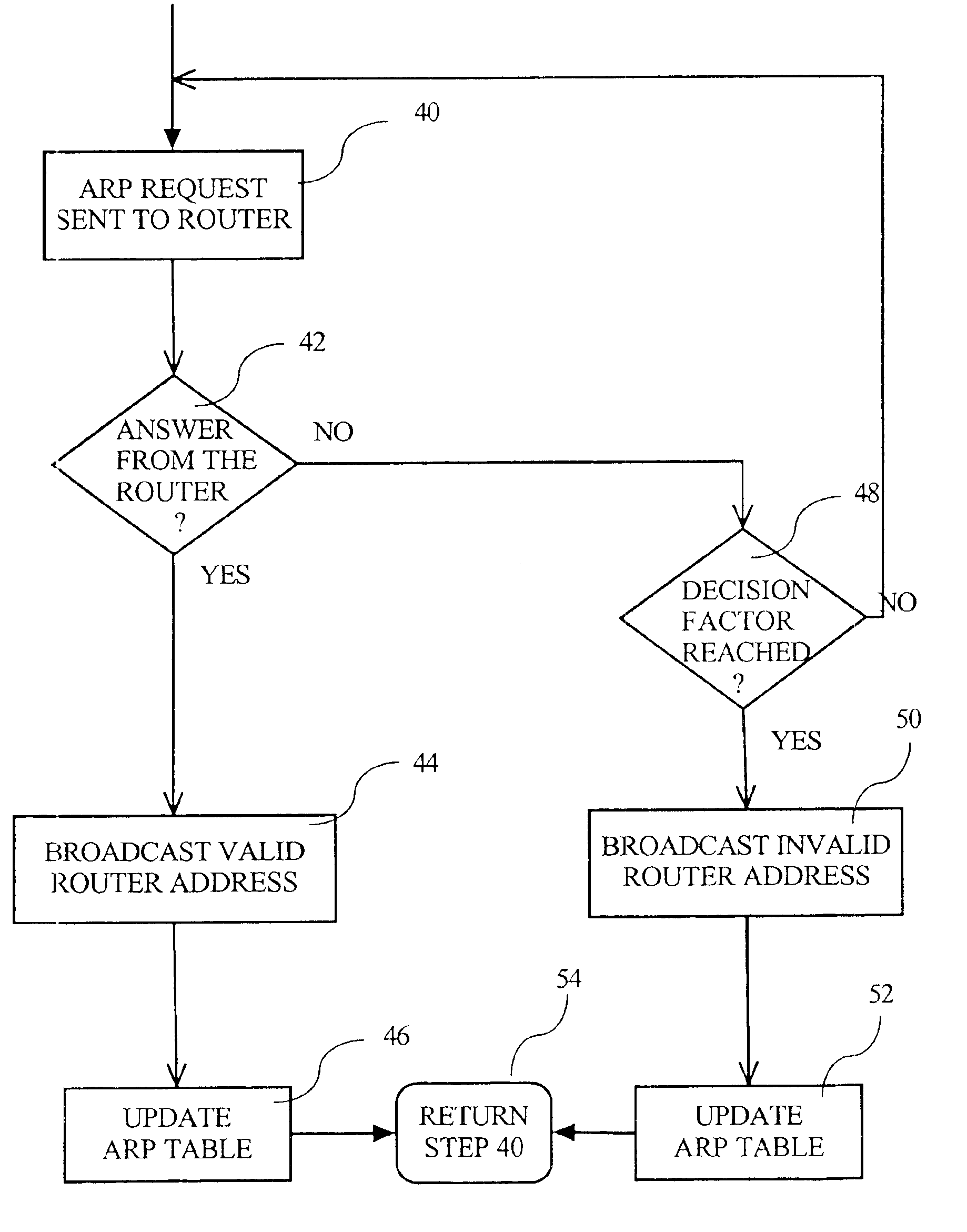
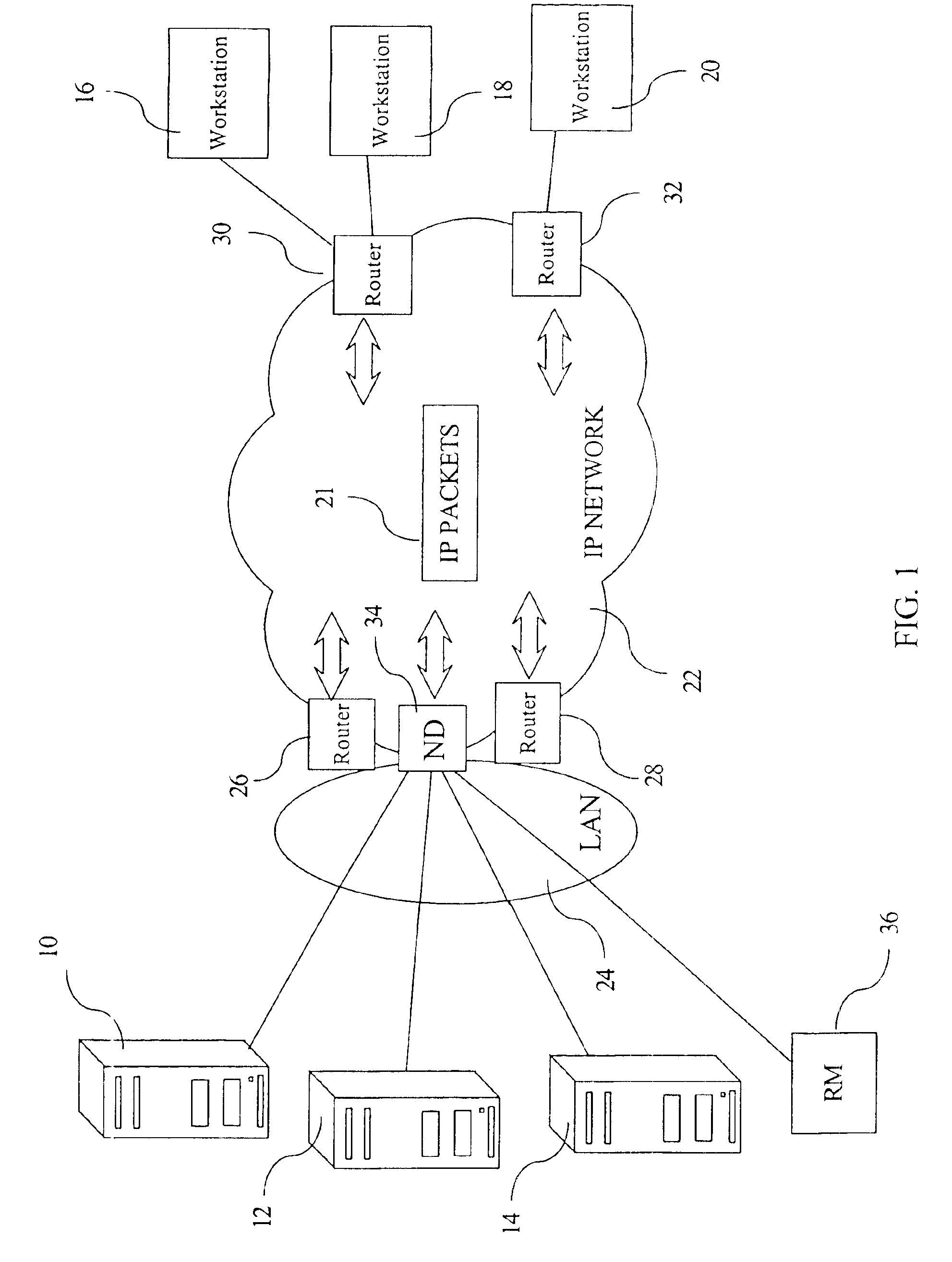
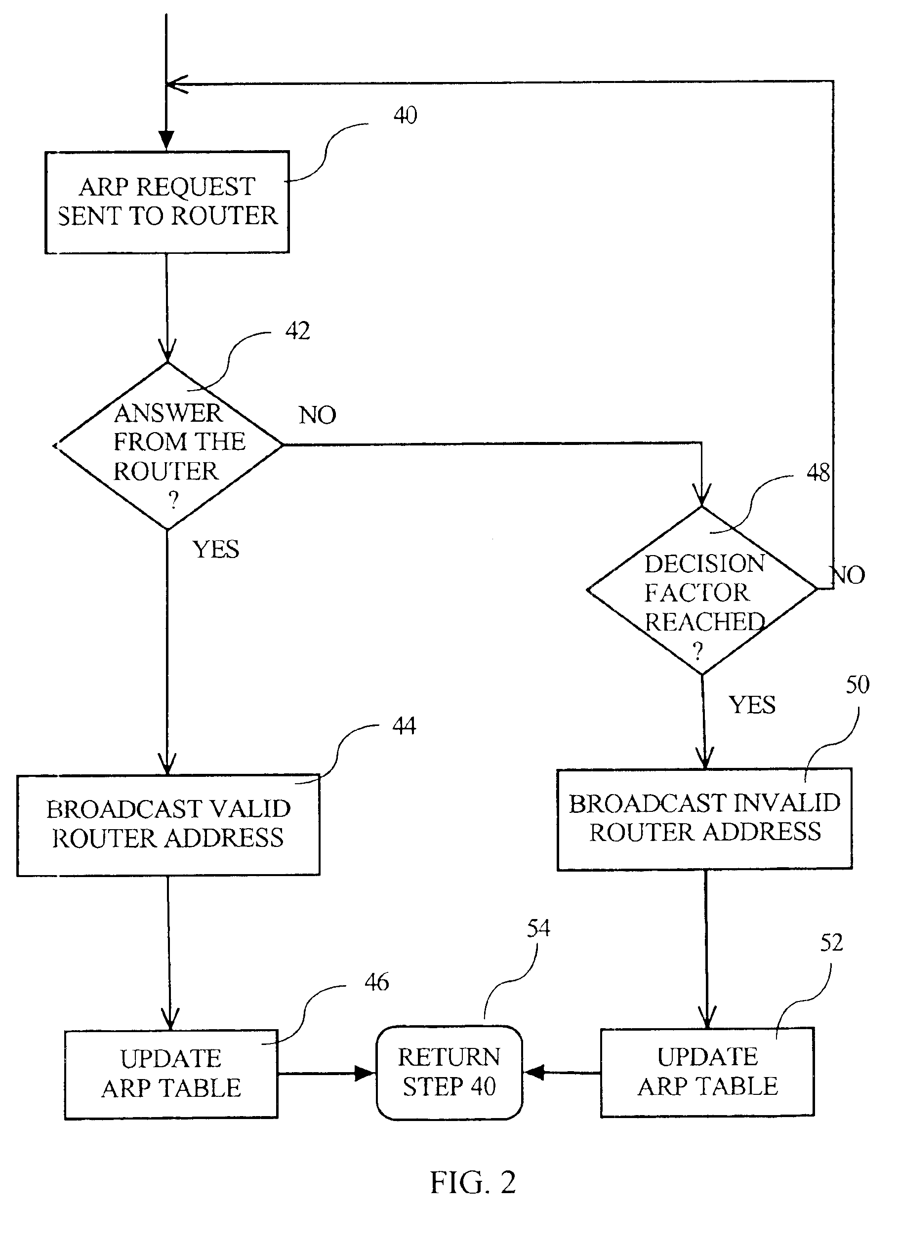
[0020]FIG. 1 illustrates embodiments of the present invention implemented in a data transmission system wherei...


PUM


Abstract

A data transmission system for exchanging packetized data between any IP host selected from a cluster of IP hosts, each host having at least an IP layer, a network layer, and a plurality of workstations coupled by an intermediary of an IP network. The IP hosts are coupled to the IP network via a layer 2 network such as a LAN interfacing the IP network by a set of routers and a network dispatcher that receives all incoming data flow and dispatches the data to the cluster of hosts. The data transmission system comprises at least a monitoring device included in the cluster of hosts where the monitoring device is operable to monitor the availability of candidate routers selected from the set of possible routers. The monitoring device also is operable for broadcasting router availability information to each host in the cluster of hosts via the network dispatcher.

Description

TECHNICAL FIELD[0001]The present invention relates in general to data processing systems, and in particular, to a new way for obtaining high availability and load balancing on default routers for IP host systems, and relates in particular to a router monitoring in such a system utilizing a network dispatcher for a cluster of hosts.BACKGROUND INFORMATION[0002]Several types of digital networks, operating with the packet switching technique in which data from different origins are chopped into fixed or variable length packets or datagrams, have been installed throughout the world. These digital networks may need to be interconnected (e.g. via routers) to optimize the possibilities of organizing traffic between source hosts and target hosts located anywhere in the world. Interconnecting such source hosts via routers is made possible by using an internetwork.[0003]Internetwork (also referred to as Internet) facilities use a set of networking protocols such as Transmission Control Protoco...

Claims


Application Information

Patent Timeline
IPC IPC(8): H04L12/26H04L29/06H04L29/12H04L12/56G06F13/00H04L12/28H04L45/586
CPCH04L12/2602H04L29/12009H04L29/12018H04L43/00H04L45/00H04L45/586H04L61/10H04L67/1002H04L43/0817H04L61/00H04L67/1001H04L12/28
Inventor LAMBERTON, MARCLEVY-ABEGNOLI, ERICSECONDO, PIERRETHUBERT, PASCAL
Owner IBM CORP
Why Eureka
Try Eureka