Spring-biased pivoting squeegee

a technology of squeegee and spring, which is applied in the field of squeegees, can solve the problems of inability to wipe off the entire window in a continuous stroke as described above, inability to clean the window, and inability to achieve the effect of wiping off the entire window in a continuous stroke, etc., and achieves low tension, improved performance, and high degree of proficiency

Inactive Publication Date: 2005-08-23
COX GRANT
View PDF16 Cites 34 Cited by
  • Summary
  • Abstract
  • Description
  • Claims
  • Application Information

AI Technical Summary

Benefits of technology

[0008]A spring having dual coils, both of which are looped around the pivot pin which joins the handle and head, is fully contained inside the head of the squeegee. Rearward projections of the spring are biased against an internal wall of the handle, and a U-shaped projection extending forward from the pivot pin into the head biases the head toward the rest position. The spring is set at a tension such that, under normal usage, the head and, hence, the wiping blade, are maintained at an angle relative to the handle; however, the tension is low enough such that, without ever removing the blade from contact with the glass surface, the head and wiping blade may be moved to the biased position by pressing down on the handle. The handle and head are prevented from over-pivoting beyond planar configuration by abutting surfaces which are brought into mutual contact when the head is moved into the biased position.
[0009]A recessed locking lever is pivotally attached to the squeegee head. The locking lever is movable about an axis generally perpendicular to the squeegee head between a locking position and an unlocked position. In the locking position, the lever is in abutting disposition with a stop on the handle. Pressure from the spring urges the lever and stop together, effectively locking the head and handle in the biased position. The pressure may be relieved by bringing slight backwards pressure against the head whereupon the lever may be rotated into the unlocked position where it is free of any obstructions, thus permitting the head to pivot back to the rest position.
[0010]A tension adjustment mechanism permits the spring tension to be adjusted to different pressure levels. A tension adjustment knob is provided on the upper surface of the squeegee head. The tension adjustment knob has a barrel fitting which sits in a well in the head to retain a knurled top portion above the upper surface of the head for manipulation by hand. A linear projection extends from the barrel fitting into the head and is in threaded engagement with a square tension adjustment nut disposed in a rectangular internal shaft in the head. As the knob is turned the nut is prevented from rotating by the walls of the rectangular shaft. Therefore, rotation of the knob moves the nut up and down in the shaft. The U-shaped projection of the spring is disposed around the linear projection and interposed between the tension adjustment knob and the tension adjustment nut. Thus, by rotating the tension adjustment knob, the U-shaped projection of the spring is lowered or raised in the head by the tension adjustment nut which adjusts the spring to a tension level suited to the ergonomic requirements of the user.
[0011]A spring-biased pivoting squeegee according to the invention can be used in the same manner as a prior art squeegee would be used in most situations. Improved performance is realized when cleaning recessed windows. As the squeegee is drawn across the window toward an abutting wall or window frame, the window washer may cause the head to move into the biased position by simultaneously pressing down on the wiping blade and forward on the handle, never removing the wiping blade from the surface of the glass. Since the wiping blade, head, and handle are all in planar disposition, the wiping motion can be continued toward the abutting wall or frame member to the edge of the glass, rather than having to remove the wiping blade from and then reapply it to the glass. Thus, an entire recessed window may be cleaned in a single continuous motion with a high degree of proficiency, leading to substantial time savings in the cleaning project, eliminating the need to use additional cleaning implements, and reducing fatigue.
[0012]An added benefit of the invention relates to the angle of the wiping blade to the glass. By maintaining the wiping blade of a squeegee at a slight angle to the perpendicular relative to the glass, the cleaning performance of the blade is superior. Therefore, the best squeegees include a slight curvature in the wiping blade mount which maintains the blade at an optimum cleaning angle. Generally, when cleaning a glass surface with a squeegee, an effort is made to hold the squeegee so that the wiping blade is retained at the optimum cleaning angle. The present invention enables the optimum cleaning angle to be retained as the squeegee is moved toward the abutting wall or frame of a recessed window, because the angle of the squeegee head to the window can be maintained by easily altering the angle of the head to the handle. The ease in adjusting the angle allows improved performance through a range of positions and provides ergonomic benefits to the user. Even at the extreme edge of a recessed window or in difficult to reach positions, the invention preserves the optimum cleaning angle and the safety of the window washer.

Problems solved by technology

Failure to swipe the surface at an optimal angle within that range will lead to streaking and visibly unsatisfactory results.
However, this conventional construction creates a problem when cleaning recessed windows.
If the window is recessed more than a few inches, or set next to a wall, wiping off the entire window in a continuous stroke as described above may not be possible, because the handle will butt against the adjacent window frame or wall.
Either alternative is less efficient than wiping a window clean in a single continuous motion and may produce streaking.
A variation of the problem arises when cleaning windows using a squeegee mounted on a pole.
If the bottom of the window is near ground level, the angle of the squeegee to the handle makes it impossible to hold the wiping blade at an optimal cleaning angle relative to the window surface.
This device also changes the orientation of the blade to the handle, which may cause an undesirable reduction in the cleaning effectiveness of the squeegee blade as it passes through the accelerating movement.
Another practical difficulty is that the kicker arm, mount, and dual fingers project from the otherwise generally contained outline of the squeegee and may interfere with or become tangled up in other equipment.

Method used


Image

  • Spring-biased pivoting squeegee
  • Spring-biased pivoting squeegee
  • Spring-biased pivoting squeegee

Examples


Embodiment Construction

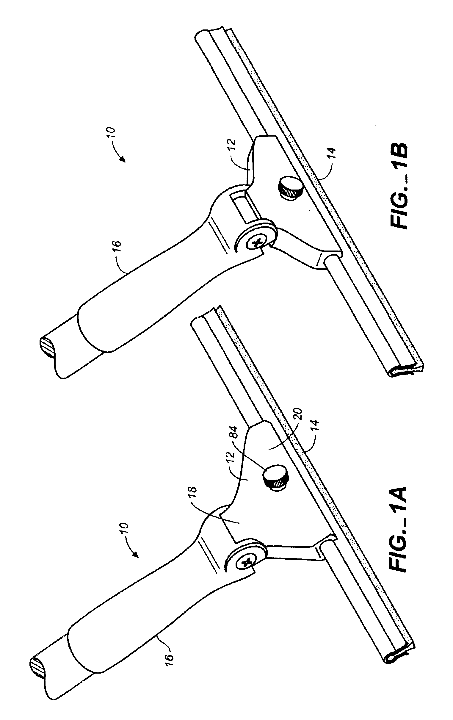
[0013]FIG. 1A is a top perspective view of a spring-biased pivoting squeegee according to the invention showing the head in the biased position relative to the handle.

[0014]FIG. 1B is a top perspective view of the pivoting squeegee of FIG. 1A, but showing the head in the rest position relative to the handle.

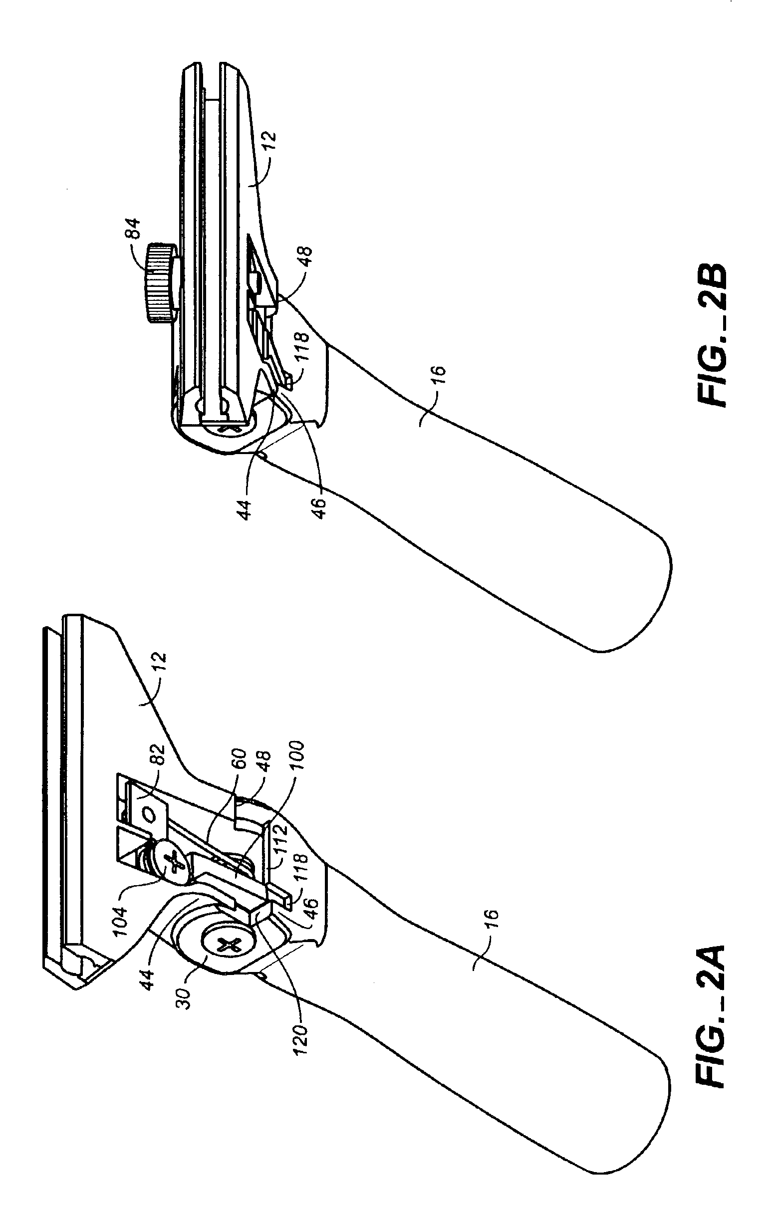
[0015]FIG. 2A is a bottom perspective view of the invention with the wiping blade removed, and showing the head in the biased position relative to the handle and the locking lever in the unlocked position.

[0016]FIG. 2B is a bottom perspective view of the pivoting squeegee shown in FIG. 2A, but with the head in the rest position relative to the handle.

[0017]FIG. 2C is an exploded perspective view of a spring-biased pivoting squeegee according to the invention.

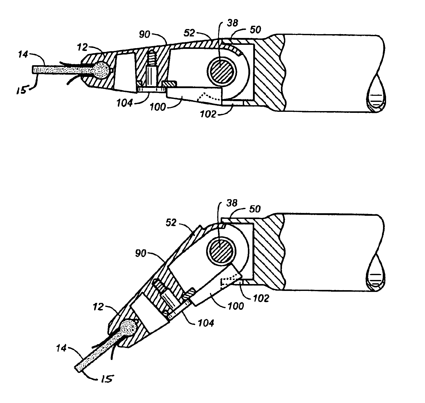
[0018]FIG. 3A is a side plan view of a pivoting squeegee according to the invention with the handle truncated, and showing the head in the biased position relative to the handle.

[0019]FIG. 3B is a side plan view of the pivoti...


PUM


Abstract

A spring-biased pivoting squeegee 10 provides a head 12 pivotally attached to a handle 16. The head 12 is movable between a rest position, in which the head 12 is angularly displaced from the handle 16, and a biased position in which the head 12, handle 16, and wiping blade 14 are in linear relation. In the biased position, the wiping blade is maintained at an optimum angle for cleaning a glass surface even with the handle 16 held generally perpendicular to the glass. A spring 60 is fully contained in the head 12 and biases the head toward the rest position. A tension adjustment knob 80 in the head 12 permits adjustment of the spring 60 to a tension level according to the ergonomic requirements of a user.

Description

FIELD OF THE INVENTION[0001]This invention relates generally to squeegees and in particular to a squeegee having a head, handle and wiping blade which can be moved into general linear relation for cleaning glass surfaces, even surfaces located in recessed corners.DESCRIPTION OF THE PRIOR ART[0002]Squeegees are widely used to clean windows quickly and effectively. Generally the cleaning process begins with wetting the window surface with water or a cleaning solution. The squeegee is then used to wipe off the water or cleaning solution and any accumulated dirt or dust leaving the window surface clean. When performed expertly, a movement sometimes known as the “butterfly stroke” is used in which the squeegee's wiping blade is initially placed along the edge of one corner of the window; then the entire surface of the window is wiped off in a continuous back-and-forth swirling motion from the top to the bottom of the window without removing the wiping blade from the surface, finishing th...

Claims


Application Information

Patent Timeline
Patent Type & Authority Patents(United States)
IPC IPC(8): A47L1/06A47L1/00B25G1/00B25G1/06
CPCA47L1/06B25G1/06Y10T16/476
Inventor COX, GRANT
Owner COX GRANT
Why Eureka
Try Eureka