Method and apparatus for centrifugal casting of metal

a centrifugal casting and metal technology, applied in the direction of molten metal conveying equipment, molten metal supply equipment, manufacturing tools, etc., can solve the problems of aeration and oxidation of metal, and achieve the effect of preventing mold warpage and rain prevention

Inactive Publication Date: 2005-08-23
NOBLE CHARLES H
View PDF17 Cites 8 Cited by
  • Summary
  • Abstract
  • Description
  • Claims
  • Application Information

AI Technical Summary

Benefits of technology

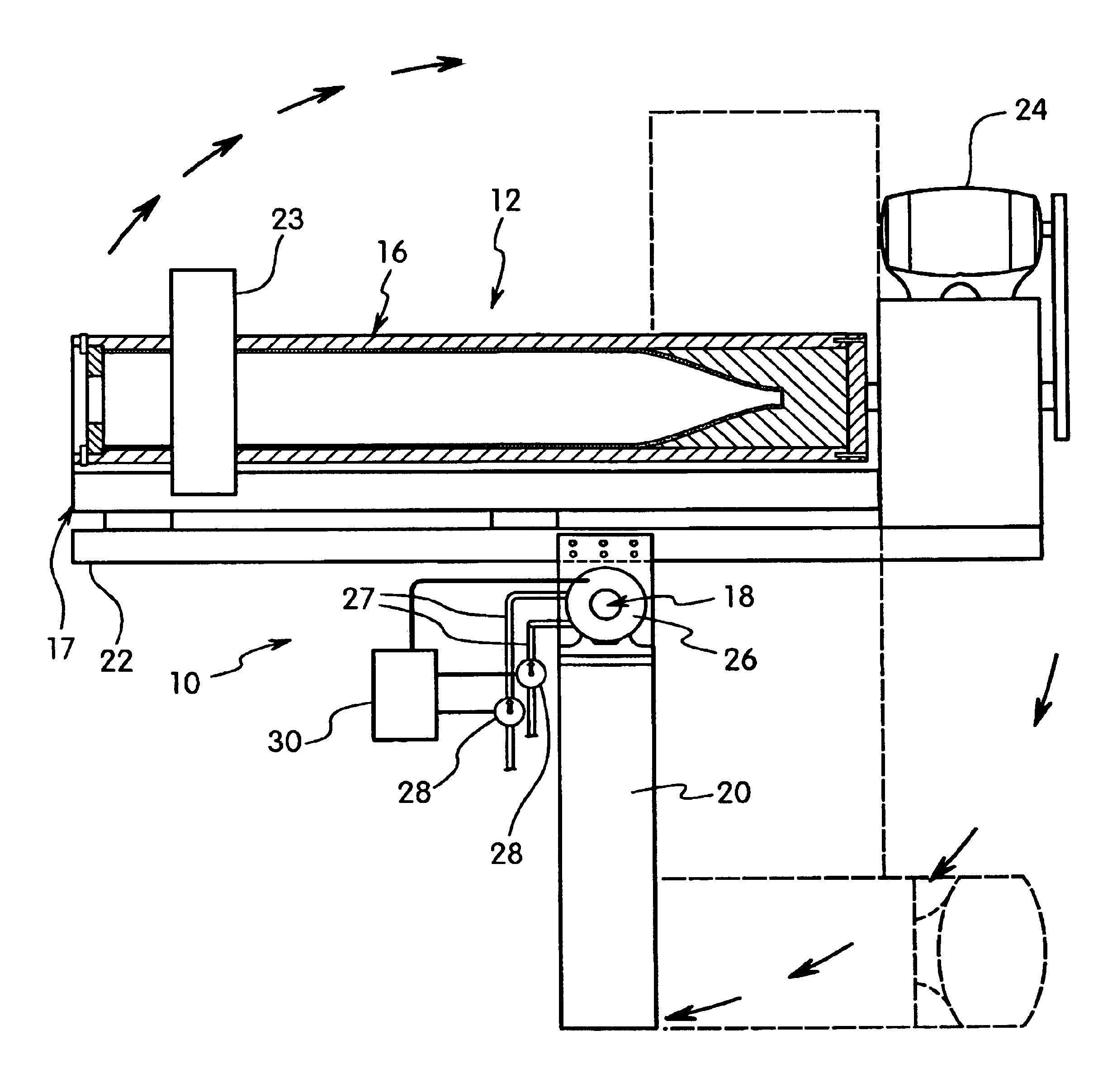
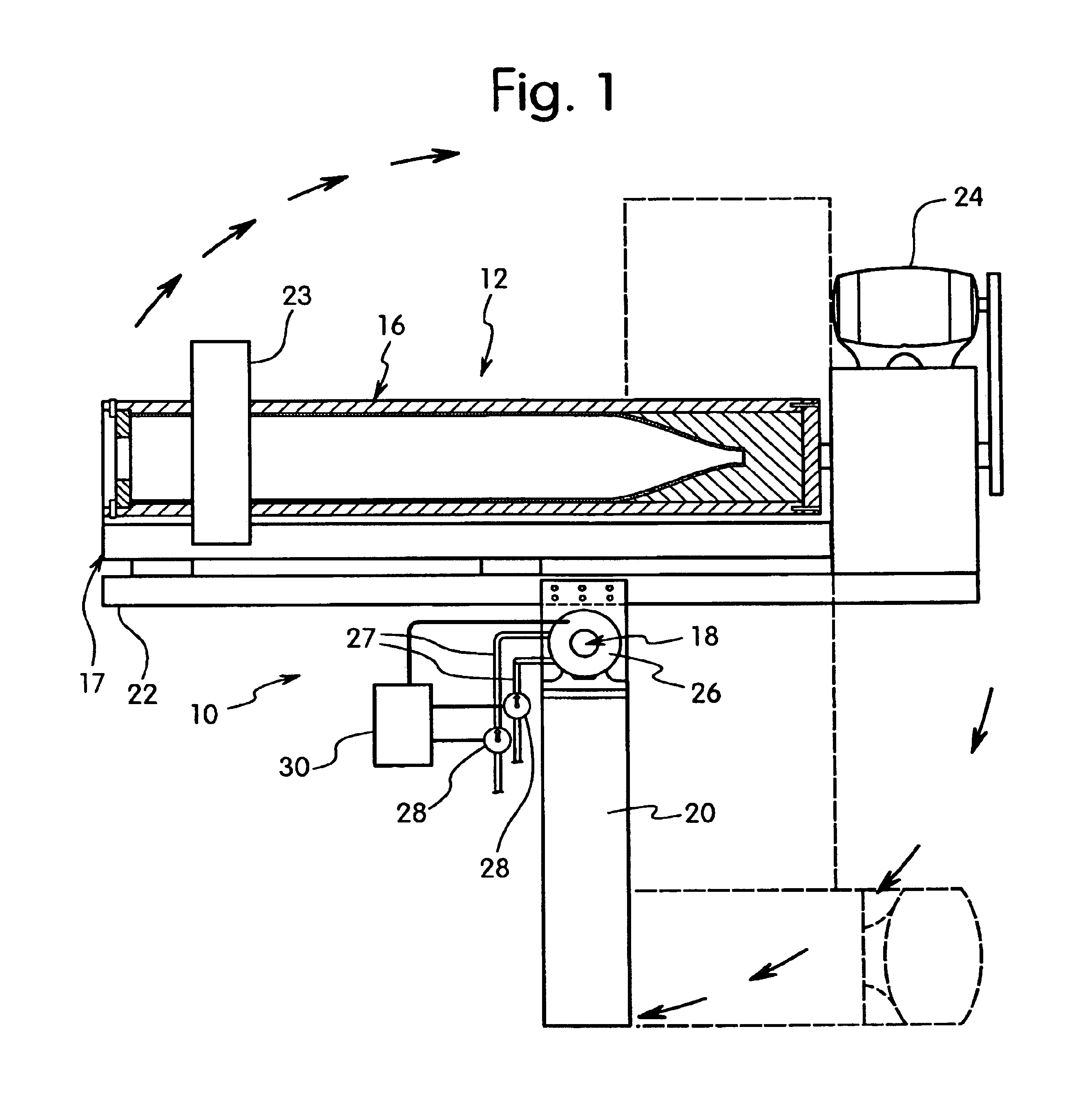
[0013]The invention is directed to a method of vertically pouring molten metal into an upended mold where all of the metal flows to the closed end of the mold. The Hybrid Centrifugal Casting Machine is near vertical when the metal is poured into the mold, slightly tilted in some degree away from vertical, to provide a mold surface to flow the molten metal into position without splashing. Pouring into a long absolutely vertical mold will cause splashing, thus aerating and oxidizing the metal. It is to be understood that the term “vertical mold” hereafter is actually slightly tilted away from vertical. This procedure will determine the pouring rate of the metal. A slow pouring rate will aid in solidifying the nose section. Therefore, pouring vertically will be pouring into a mold slightly tilted off true-vertical, but will have the pouring benefit of the vertical casting process of turbulent-free pouring. The mold can be stationary or it can be slowly rotated to generate less than one gravity of force to prevent raining. This will distribute the heat evenly and prevent the mold from warping.
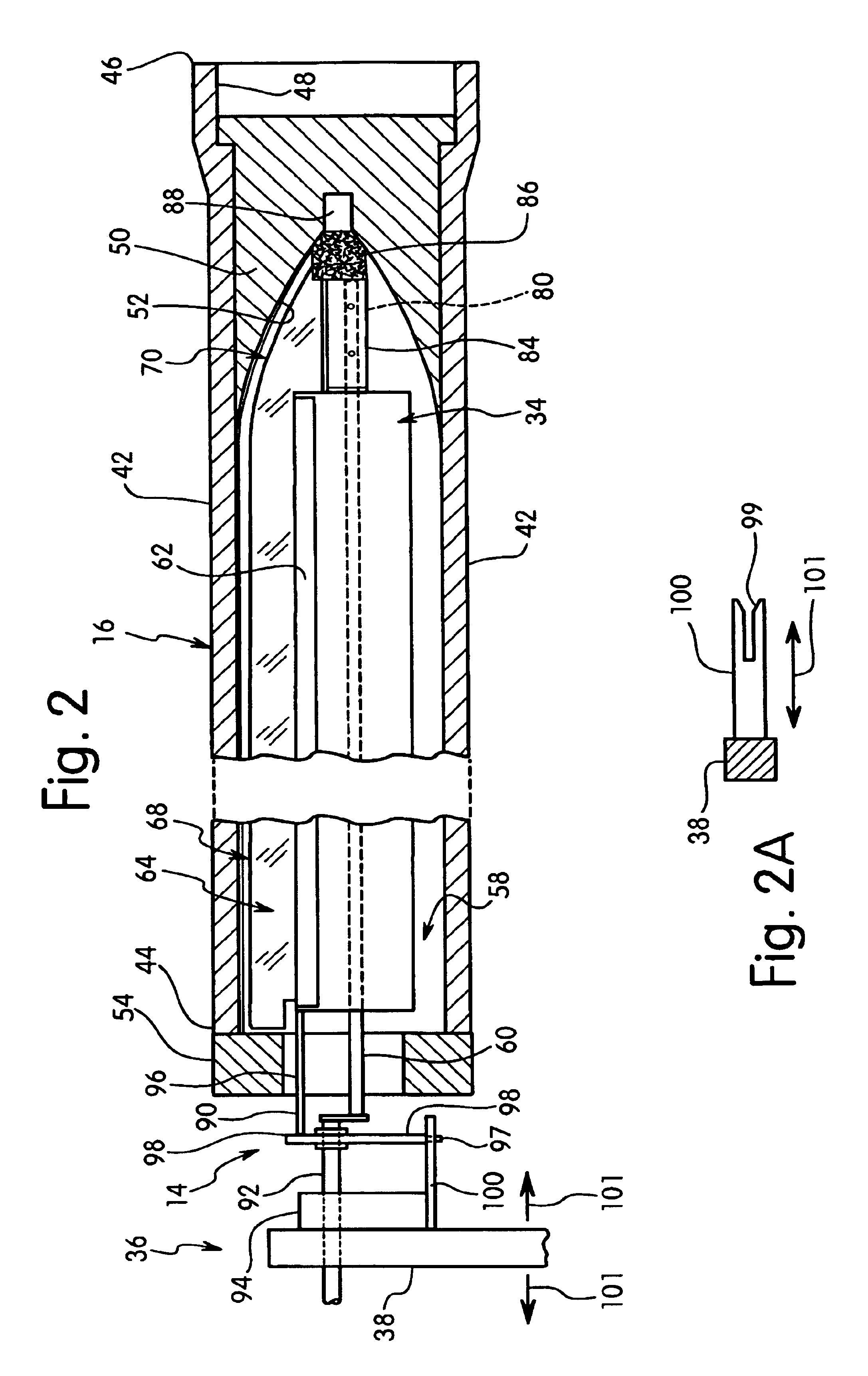
[0020]Therefore, the capability to alter the angle that the flat end of the blade engages the refractory allows the use of a single combination blade having the flat end surface machined to the dimensions of the article, thus cutting the trough operating time in half.

Problems solved by technology

Pouring into a long absolutely vertical mold will cause splashing, thus aerating and oxidizing the metal.

Method used


Image

  • Method and apparatus for centrifugal casting of metal
  • Method and apparatus for centrifugal casting of metal
  • Method and apparatus for centrifugal casting of metal

Examples


Embodiment Construction

[0039]The present invention is directed to a method and apparatus for molding a metal article. The invention is particularly suitable for the centrifugal casting of metal to form hollow articles that are closed on one end.

[0040]The apparatus of the invention is a centrifugal casting machine that casts the metal in a vertical orientation and a horizontal orientation. For this reason, the apparatus is referred to herein as a hybrid centrifugal casting apparatus.

[0041]The molding apparatus includes a substantially cylindrical shaped mold body having a closed bottom end. The mold body is initially oriented in the vertical position with the mold rotating about its longitudinal axis. An amount of molten metal is added to the mold cavity where centrifugal force places the molten metal into the mold wall without turbulence and the mold body is pivoted to a horizontal or inclined position to distribute the metal along the length of the mold body. When the metal cools and solidifies, the arti...


PUM

PropertyMeasurementUnit
weightsaaaaaaaaaa
lengthsaaaaaaaaaa
lengthsaaaaaaaaaa

Abstract

A method and apparatus for centrifugal casting of metal articles uses a rotating mold body that can be pivoted from a vertical orientation to a horizontal orientation during the centrifugal casting of the metal article. The resulting metal article has a closed end and an open end defining a hollow cavity. The mold body has a closed end that is oriented in a vertical position with the longitudinal axis extending vertically. While the mold body is rotated, an amount of molten metal is introduced into the mold body so that the molten metal is distributed along the closed end of the mold body. In one embodiment, the bottom end of the mold body has a frustoconical shaped surface defining the mold cavity. The mold body is then pivoted to a horizontal position while continuously rotating to distribute and cast the metal against the inner surface of the mold body. In one embodiment, the mold body has a refractory lining of a compacted refractory material. The refractory material is introduced into the rotating mold and a blade is contacted with the layer of the refractory material formed on the inner surface while the mold is rotated in a first direction to compact and densify the layer of particles with a flat end of the blade. The rotation of the mold body is then reversed and the sharp edge of the blade is contacted with the compacted layer to shape and contour the mold lining.

Description

[0001]This application is a continuation-in-part of U.S. patent application Ser. No. 10 / 720,689, filed Nov. 25, 2003 now abandoned, which claims the benefit of U.S. Provisional Application No. 60 / 428,745 filed Nov. 25, 2002, which applications are hereby incorporated by reference in their entirety.FIELD OF THE INVENTION[0002]The present invention is directed to a method for pouring horizontally cast, long thick wall tubular articles having a straight bore.[0003]The invention is also directed to an improved method for pouring horizontally cast, long thick wall tubular articles of straight bore, closed on one end, such as a bomb body.[0004]This invention is an improved method for pouring horizontally cast long thick wall tubular articles having a straight bore closed on one end, and a tapered bore closed on one end. According to the method of this invention, molten metal is poured into a near vertical mold to prevent splashing and the mold is transitioned from the vertical position to...

Claims


Application Information

Patent Timeline
Patent Type & Authority Patents(United States)
IPC IPC(8): B22D13/00B22D13/02
CPCB22D13/02
Inventor NOBLE, CHARLES H.
Owner NOBLE CHARLES H
Why Eureka
Try Eureka