Lubrication device

Inactive Publication Date: 2005-08-23
LINCOLN GMBH
View PDF22 Cites 3 Cited by
  • Summary
  • Abstract
  • Description
  • Claims
  • Application Information

AI Technical Summary

Benefits of technology

[0004]It is an object of the present invention to propose a lubrication device of the abov

Problems solved by technology

With such known lubrication devices, difficulties occur with lubrication site speeds above a predetermined limit valu

Method used


Image

  • Lubrication device
  • Lubrication device
  • Lubrication device

Examples


Embodiment Construction

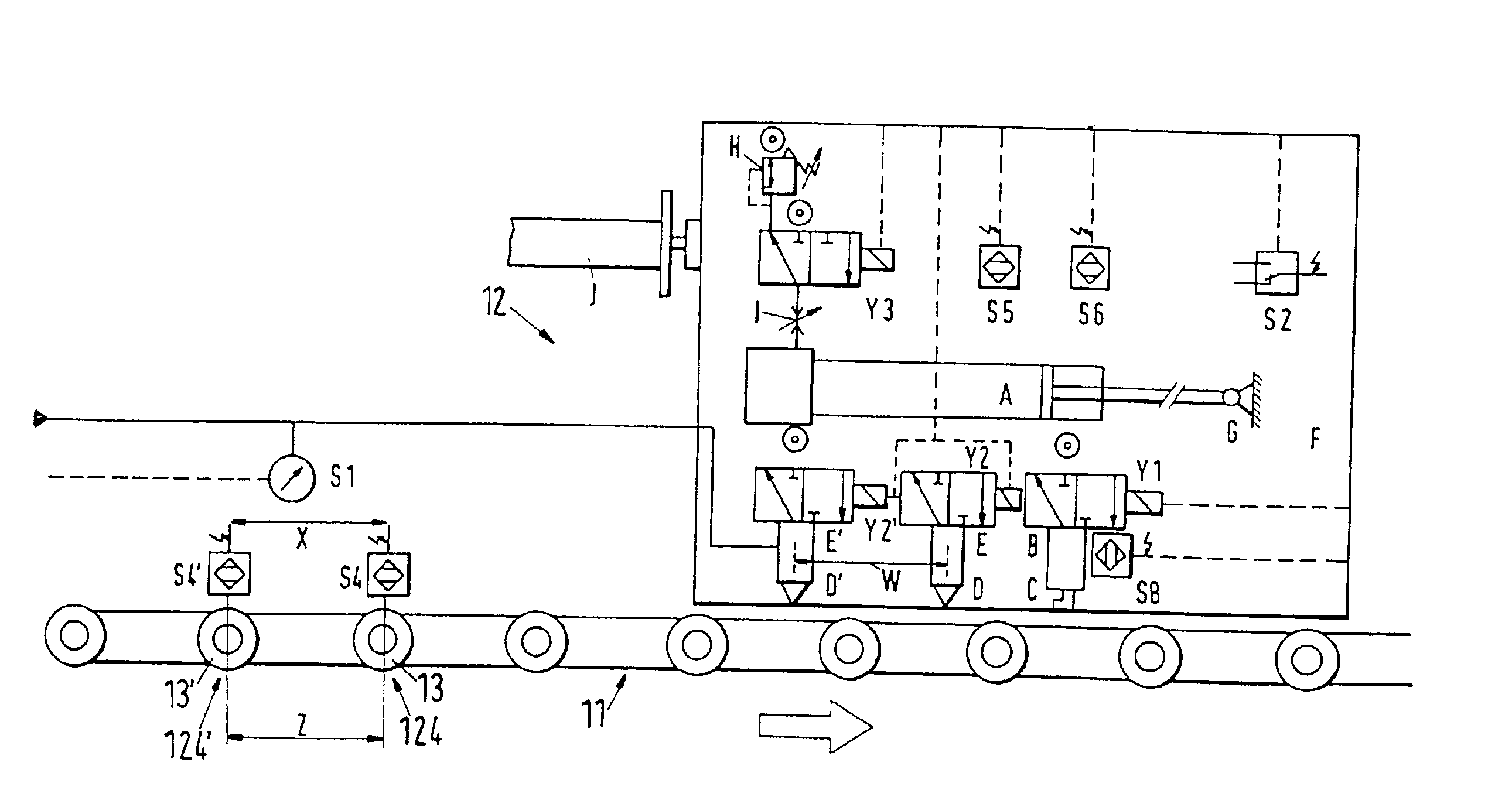
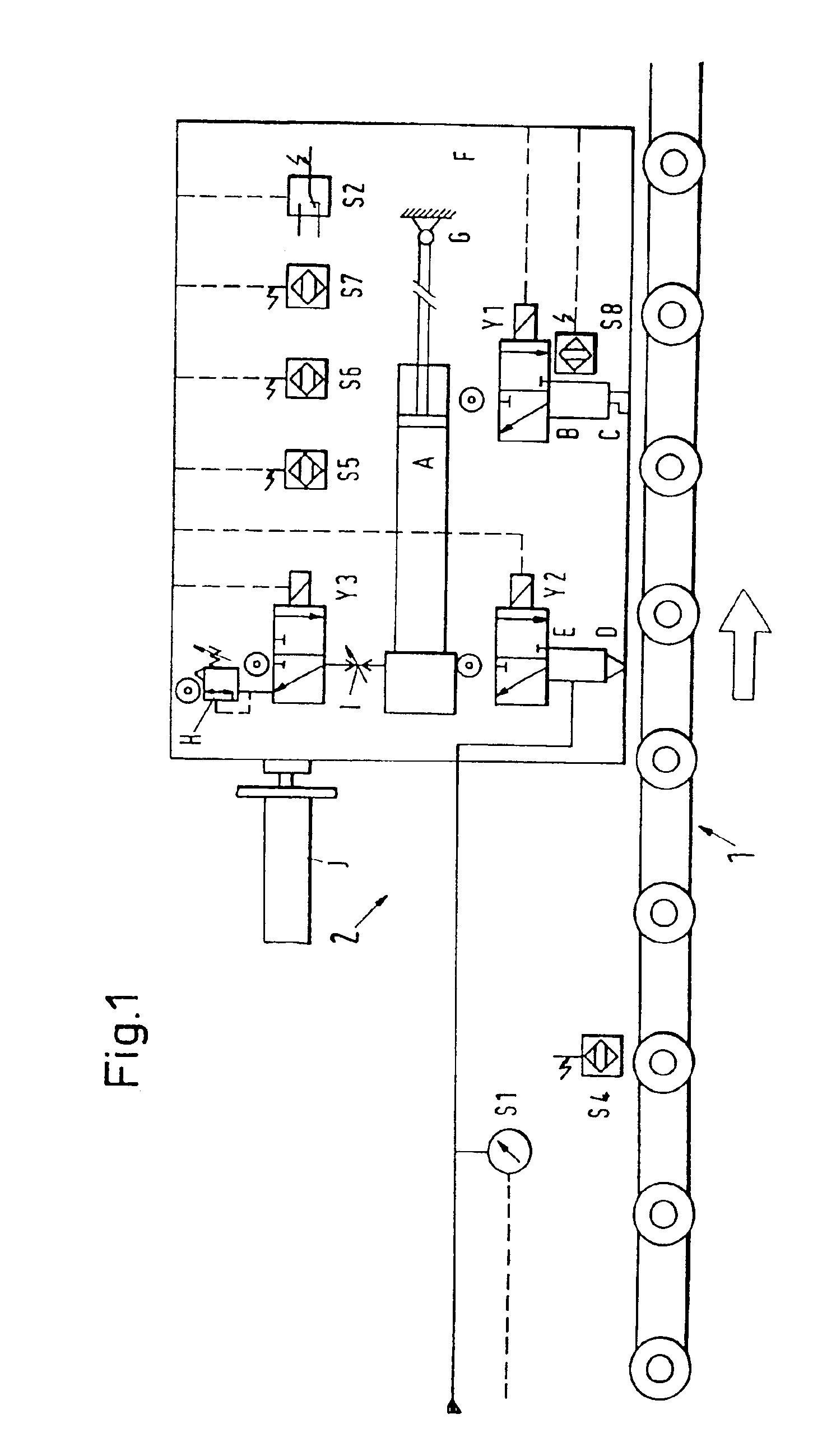
[0047]The graphically represented lubrication device serves for lubricating traveling lubrication sites, for example on a roller and chain belt 1. To supply the lubrication device, lubricant is supplied from a central lubrication pump. The driving of the pump takes place via a pressure switch S1 with two switching points: p≦pmin (pump on) and p≧pmax (pump off). At the beginning of the lubrication process, a proximity switch S5 is switched in order to indicate the operational readiness of the lubrication device.

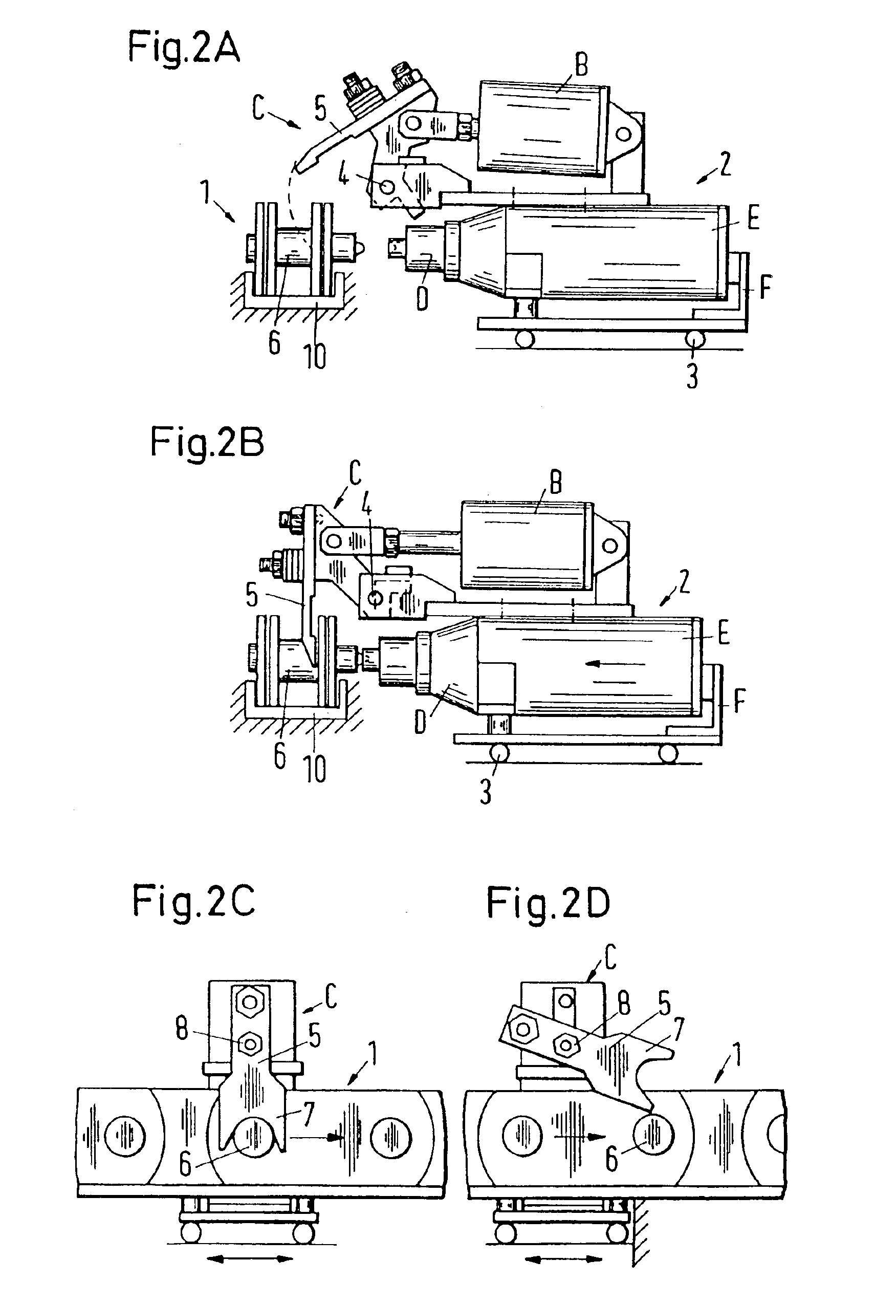
[0048]A proximity switch S4 inductively acquires the position of a traveling lubrication site, for example a tread roller, which is to be lubricated, and switches therein a 3 / 2-way valve Y1. Air pressure is thereby placed into a catch cylinder B and a catch C is pushed outward. The sequence of the lubricating processes (i.e., whether or not, for example, every tread roller or every second tread roller is to be lubricated) depends on the number of tread rollers and on the speed...


PUM


Abstract

A lubrication device lubricates traveling lubrication sites, such as on a belt (1), in particular, on a roller or chain belt (1). The lubrication device includes a lubricating apparatus (2) having a catch (C) that is capable of assuming a resting position and a catching position relative to the belt (1). In the catching position, a lubricating head (D) of the lubricating apparatus (2) is moved to a lubrication site by relative lateral motion between the belt (1) and the lubricating apparatus (2) in order to supply lubricant to the lubricating site. At the end of the run path, the lubricating head (D) as well as the catch (C) moves relative to the belt (1) to return back to the resting position. Also, before or simultaneously while the catch (C) is brought into engagement with the belt (1), the lubricating apparatus (2) can be extended in a longitudinal direction of the lubrication site motion at a boosting speed, which is greater than zero and less than the speed of the belt (1).

Description

[0001]This application is a divisional application of Ser. No. 09 / 950,080 filed Sep. 12, 2001, now U.S. Pat. No. 6,742,625.BACKGROUND OF THE INVENTION[0002]The invention relates to a lubrication device for lubricating traveling lubrication sites, such as those on a belt (such as a roller or chain belt), which comprises a lubricating apparatus supported so as to be displaceable back and forth in the longitudinal direction of the lubrication site motion. The lubricating apparatus includes a catch assuming a resting position and a catching position relative to the belt a similar component having the lubrication sites. The belt drives the catch in the catching position and thus drives the catch along the lubricating apparatus over a predetermined run path at the speed of the belt. A lubricating head can be moved through a lateral relative motion between the belt and the lubricating apparatus to a lubrication site, and lubricant can be supplied to At the end of the run path, the lubricat...

Claims


Application Information

Patent Timeline
IPC IPC(8): B65G45/00B65G45/08F16N7/38F16N7/00F16N29/00F16N29/02
CPCB65G45/08F16N7/38F16N29/02F16N2210/24F16N2210/33
Inventor RODEMER, KARLRUHL, HEINZ
Owner LINCOLN GMBH
Why Eureka
Try Eureka