Railing

a technology for railings and railings, which is applied in the direction of wire networks, other domestic articles, wire articles, etc., can solve the problems of reducing affecting the service life of the rail, so as to achieve the effect of tight friction or force fit and minimum time and labor

Inactive Publication Date: 2005-08-23
HARDER WILLARD J
View PDF11 Cites 35 Cited by
  • Summary
  • Abstract
  • Description
  • Claims
  • Application Information

AI Technical Summary

Benefits of technology

[0010]The invention comprises a railing for a deck and stair having top and bottom rails connected to upright posts anchored to supports. Upright spindle members extended between the top and bottom rails have opposite ends located in surface contact with flat members positioned on the rails. Ball knobs or ball connectors engage the flat members. Fasteners, such as deck screws, secure the knobs to the rails and maintain the knobs in firm engagement with the flat members. The spindle members are cylindrical metal tubes, such as coated aluminum tubes. The spindle members can be square or multi-sided metal or plastic tubes. The opposite ends of the spindle members are telescoped over the knobs to anchor and retain the spindle members in fixed upright positions between the top and bottom rails. The ball knobs have hemispherical configurations with a size to accommodate the inside walls of the spindle members with a tight friction or force fit. The opposite ends of the spindle members have end surfaces located in surface engagement with the flat members which space the tubes from the rails. The tight friction fit relation between the ball knobs and inside walls of the spindle members provide seals to prevent moisture, water, dust, and first from entering the spaces with the spindle members. The ball knobs have a plurality of outwardly directed annular ribs which flex inwardly when the spindle members are mounted on the ball knobs. The ribs are located in planes normal to the axis of the hole through the body of the ball knob. The ribs are separate sealing rings located in a force fit biased relation with the inside walls of the spindle members. Ball knobs in an alternate embodiment have continuous external convex surfaces that are in a tight friction or compression fit with the inside walls of the spindle members. The ball knobs allow the spindle members to be moved to inclined positions relative to the rails without modifications or additional structures or welds. the knobs are ball connectors which can be secured directly to the top and bottom rails. The spindle members mounted on the ball knobs extend between and engage the top and bottom rails. An alternate embodiment of the spindle member comprises an elongated metal or plastic tube having an inside cylindrical wall with inwardly directed longitudinal projections or ribs. The projections are forced into the sides of the ball knobs when the spindle members are pressed onto the ball knobs. The projections prevent the spindle members from rotating relative to the ball knobs. The ball knobs are installed on the rails with a minimum of time and labor and with conventional tools. The ends of the spindles cover the ball knobs rendering the railing aesthetically pleasing and decorative.

Problems solved by technology

A substantial amount of time, labor and craftsmanship is employed to assemble and construct deck and stair railings.
Over time, copper corrodes aluminum causing the spindles break away from the rails.
The shank connectors do not allow angular adjustment of the tubular members relative to a rail.
The connectors do not permit angular adjustment of the spindle members relative to the rail.

Method used


Image

  • Railing
  • Railing
  • Railing

Examples


Embodiment Construction

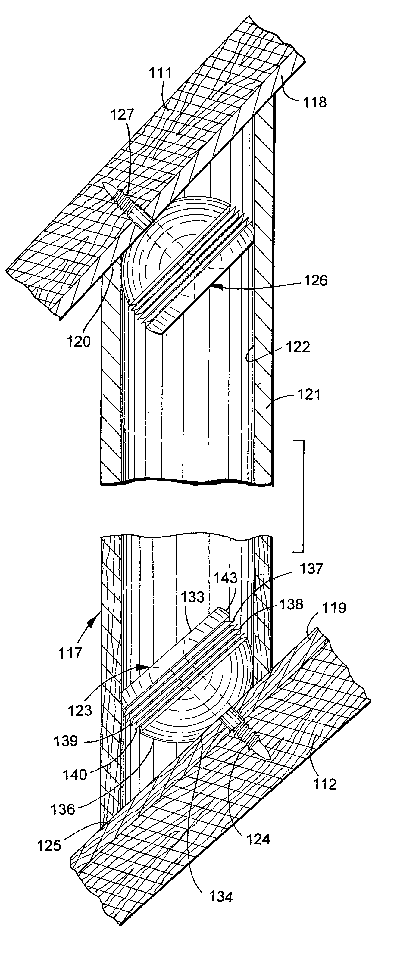
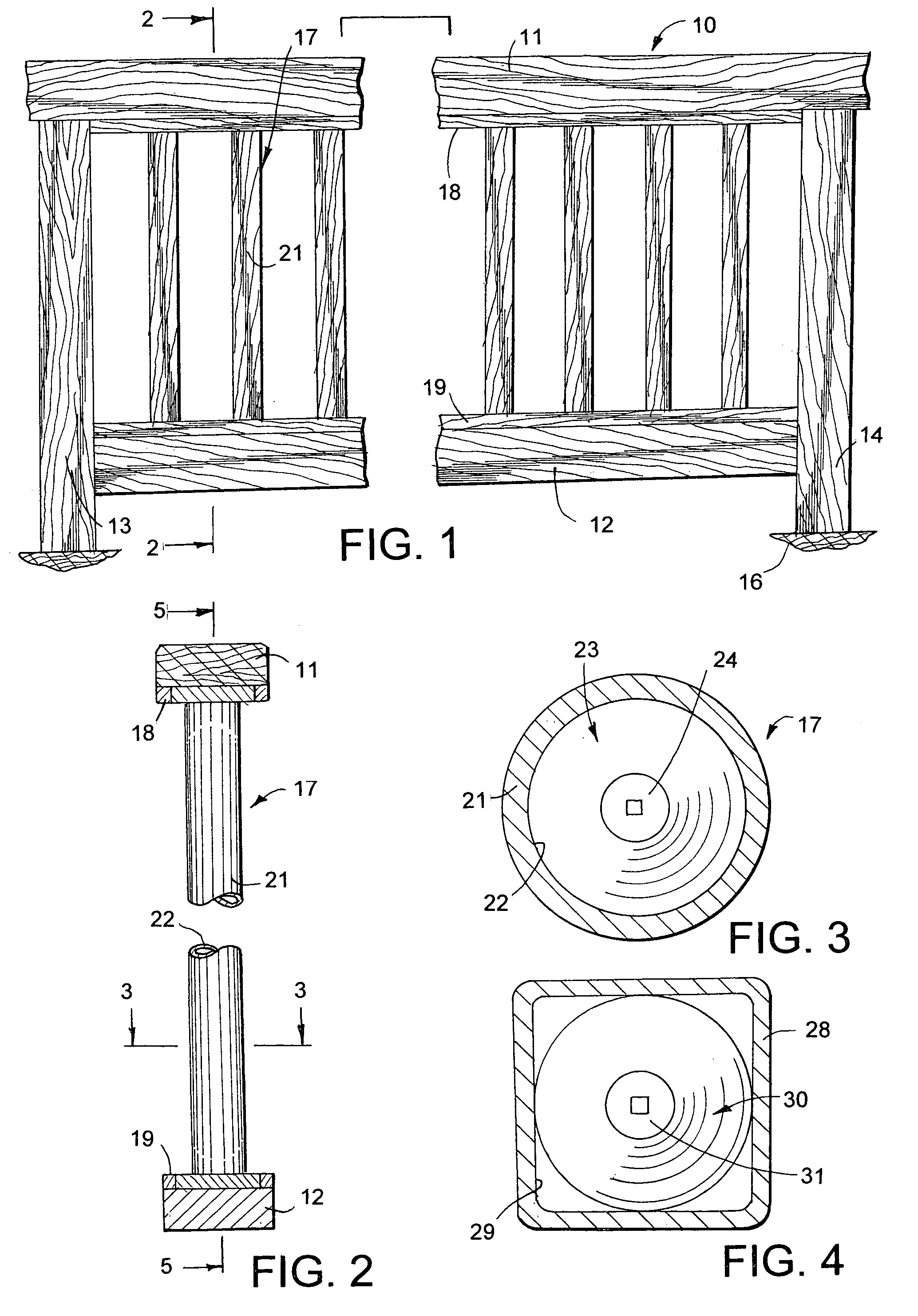
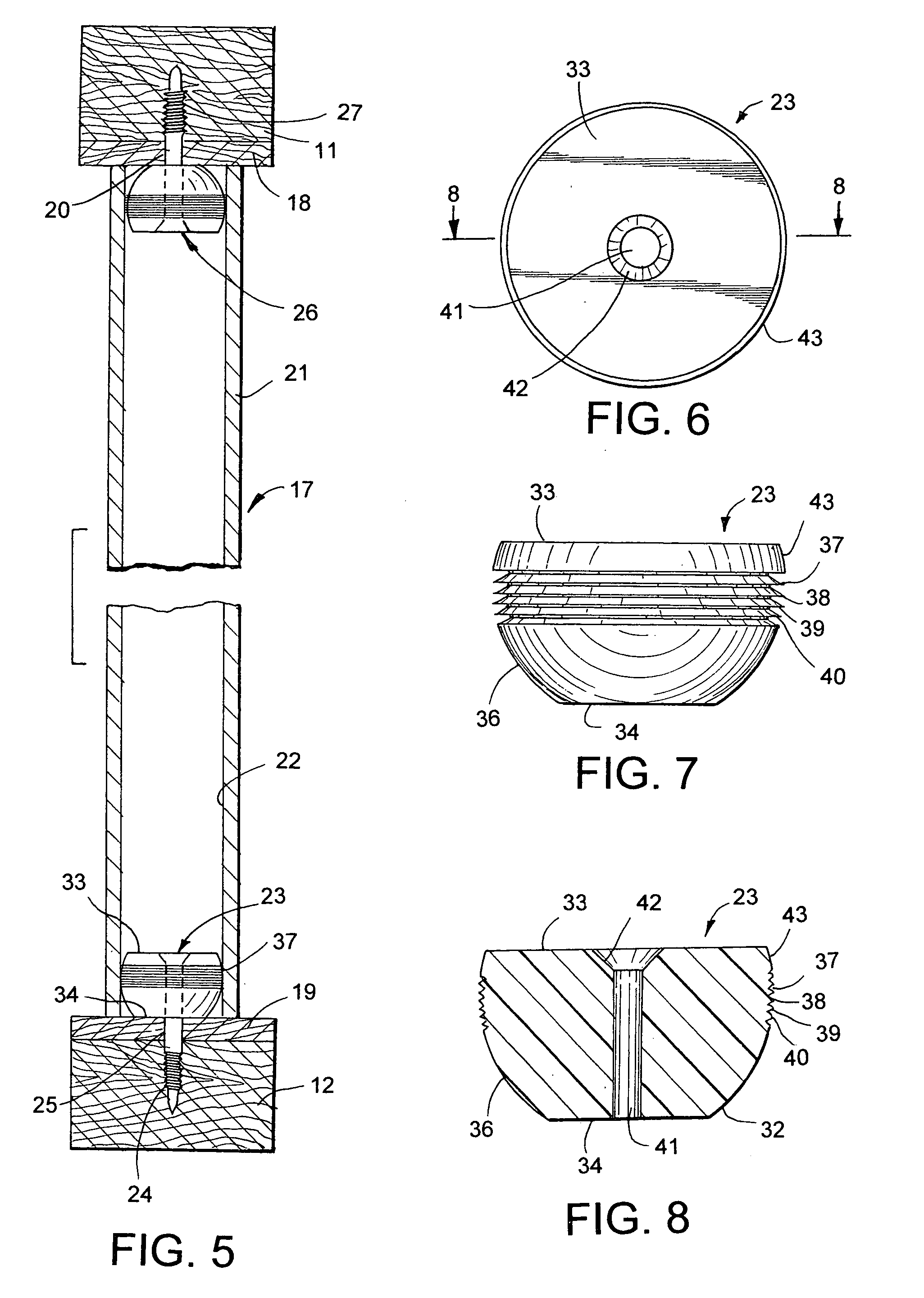
[0040]A railing 10, shown in FIG. 1, has horizontal top and bottom rails 11 and 12 joined to upright columns or posts 13 and 14 providing a generally rectangular opening for a plurality of laterally spaced spindles or balusters 17. Posts 13 and 14 are anchored to a support 16, such as a floor, deck, or ground. Rails 11 and 12 and posts 13 and 14 are conventional wood members. Plastic, metal and composite materials can be used for the rails and posts. The spindles 17 comprise laterally spaced upright cylindrical tubes or linear tubular members 21. Tubular members 21 are metal tubes, such as aluminum tubes. Other materials, such as plastic or composite materials, can be used for spindles 17. A plurality of laterally spaced upright linear tubes 21 are located between rails 11 and 12. The opposite ends of the tubes 21 are retained with ball connectors or ball knobs 23 in surface engagement with flat plates 18 and 19 located in surface engagement with top and bottom rails 11 and 12 to sp...


PUM


Abstract

A deck and stair railing has top and bottom rails joined to upright posts and upright tubes extended between the rails. Ball knobs mounted on plates or the rails are secured with deck screws to the rails to retain the tubes in assembled relation with the rails. The ball knobs have circumferential ribs located in force fit relation with inside surfaces of the tubes. The tubes have projections that engage the ball connectors to prevent the tubes from rotating relative to the ball connectors.

Description

RELATED APPLICATION[0001]Applicant claims the priority date of U.S. Provisional Patent Application Ser. No. 60 / 418,280 filed Oct. 15, 2002.FIELD ON THE INVENTION[0002]The invention is the art of railings, fences and barriers used to separate environmental areas. The particular field of the invention relates to residential and commercial railings having upright laterally spaced balusters or spindles attached to rails.BACKGROUND OF THE INVENTION[0003]Residential decks and stairs have railings to separate these structures from adjacent areas and prevent persons from falling off the decks and stairs. The railings have top rails support on upright posts attached to the decks and stairs. A number of laterally spaced upright members, known as balusters, spindles or pickets, extend between the top rails and decks and stairs. Wood upright members are fastened to the rails with nails, screws and adhesives. Dowel-type joints are also used to connect opposite ends of wood upright members to top...

Claims


Application Information

Patent Timeline
Patent Type & Authority Patents(United States)
IPC IPC(8): E04H17/14E04F11/18
CPCE04F11/1834E04F2011/1887E04F11/1817E04F2011/1819E04F2011/1821E04F2011/1823E04F2011/1827
Inventor HARDER, WILLARD J.
Owner HARDER WILLARD J
Why Eureka
Try Eureka