Suction cup universal handcart crank

A suction cup type and handcart technology, which is applied in the direction of pull-out switchgear, electrical components, switchgear, etc., can solve the problems of increasing operation output, low versatility, and inconvenient carrying, so as to prevent the crank handle from falling off and ensure the swing Good efficiency and versatility

Active Publication Date: 2020-07-24
PANZHIHUA POWER SUPPLY COMPANY STATE GRID SICHUAN ELECTRIC POWER
View PDF7 Cites 0 Cited by
  • Summary
  • Abstract
  • Description
  • Claims
  • Application Information

AI Technical Summary

Problems solved by technology

In actual use, the handcart crank has the following disadvantages: 1) low versatility: the parameters of the handcart crank of different types of switch cabinets are different; 2) inconvenient to carry: the existing handcart crank is an integrated structure and cannot be disassembled , not easy to carry in the operation bag; 3) The operation process is laborious: the handle of the handcart swings up and down or left and right during the operation, in order to obtain a suitable torque to push the handcart circuit breaker, the operation must be increased during the operation; 4 ) Low operating efficiency: due to the laborious operation process, when the same operator performs multiple operations continuously, the operation time will increase significantly; 5) Easy to fall off: due to the uneven force of the operator in the process of rotating the handle, the lead screw will be overturned. Shaking, so that the crank handle is separated from the handcart, there is a big safety hazard

Method used


Image

  • Suction cup universal handcart crank
  • Suction cup universal handcart crank
  • Suction cup universal handcart crank

Examples


Embodiment Construction

[0026] The technical solutions in the embodiments of the present invention are clearly and completely described below in conjunction with the accompanying drawings of the present invention. Apparently, the described embodiments are only some of the embodiments of the present invention, not all of them. Based on the embodiments of the present invention, all other embodiments obtained by persons of ordinary skill in the art without making creative efforts belong to the protection scope of the present invention.

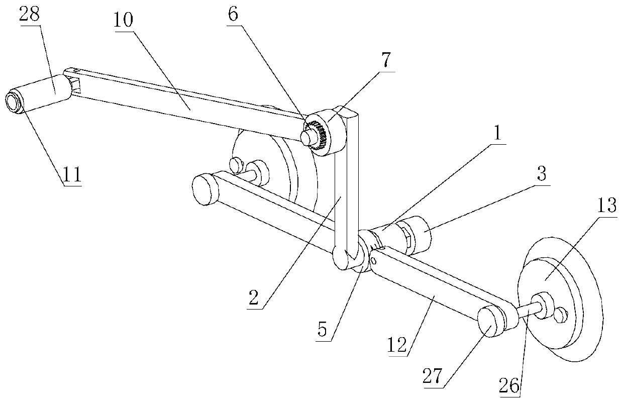
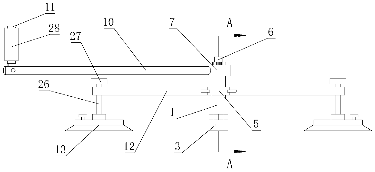
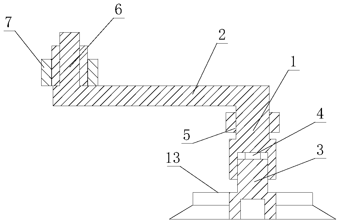
[0027] combine Figure 1-7 , a kind of sucker-type universal handcart handle, including a sleeve rod 1 as the rotation center of the handcart handle, and one end of the sleeve rod 1 is radially fixed with a first handle rod 2; that is, at one end of the sleeve rod 1 A first handle 2 is fixed, and the length direction of the first handle 2 is located in the plane where the radial section of the sleeve rod 1 is located. The part where the first handle 2 is connected to t...


PUM


Abstract

The invention relates to the technical field of power supply equipment accessories, and aims to provide a sucker type universal handcart rocking handle. The technical scheme adopted is as follows: thesucker type universal handcart rocking handle comprises a sleeve rod, wherein a first handle rod is radially fixed at one end of the sleeve rod, a connecting hole matched with the screw rod rotatingsleeve is formed at the other end of the sleeve rod, and a support ring is sleeved in the middle of the sleeve rod; the other end of the first handle rod is fixed with an adjusting rod, the adjustingrod is parallel to the sleeve rod and is respectively arranged at two sides of the first handle rod, an adjusting ring is sleeved outside the adjusting rod, and a plurality of bulges and recesses, which are matched with each other, extend along the axial direction of the adjusting rod and are uniformly distributed on the circumference, are respectively arranged on the side walls of the adjusting rod and the adjusting ring which are contacted; a second handle rod is radially fixed on the side wall of the adjusting ring, and a handle is arranged at the other end of the second handle rod; the support ring is radially connected with a support rod, one end of the support rod opposite to the sleeve rod is provided with a sucker, and the axis of the sucker is parallel to and on the same side as the sleeve rod. The sucker type universal handcart rocking handle can adjust the effective length of the handle and replace the screw rod rotating sleeve according to a specific handcart, and has the characteristics of portability, labor-saving property, high efficiency, anti-falling property and universality.

Description

technical field [0001] The invention relates to the technical field of power supply equipment accessories, in particular to a suction cup-type universal handcart crank. Background technique [0002] In recent years, with the rapid development of regional economy, the construction of urban distribution network is also planning ahead. The handcart circuit breaker is widely used in the design of urban distribution network due to its small footprint and simple structure. However, according to the regulations in the "State Grid Corporation of Safety Equipment Use Specifications", the handcart handle must be used to break the circuit device to operate. In the existing handcart circuit breakers, the operating parts are placed on the frame of the chassis, and the withdrawal and insertion of the frame on the power distribution cabinet / switch cabinet is realized by rotating the screw rod of the chassis, so as to realize the dynamic contact and static contact. Head disconnection and ...

Claims


Application Information

Patent Timeline
Patent Type & Authority Patents(China)
IPC IPC(8): H02B11/02H02B11/167
Inventor 胡刚章有军刘雨田唐彬淋尹雪飞
Owner PANZHIHUA POWER SUPPLY COMPANY STATE GRID SICHUAN ELECTRIC POWER
Why Eureka
Try Eureka