Signal light and rear-view mirror arrangement

a technology for rear-view mirrors and signal lights, applied in fixed installation, lighting and heating devices, transportation and packaging, etc., can solve the problems of unsatisfactory function design of rear-view mirror signal lights, and achieve the effect of high light intensity for indication

Inactive Publication Date: 2005-08-23
HUANG JEAN SAN
View PDF9 Cites 81 Cited by
  • Summary
  • Abstract
  • Description
  • Claims
  • Application Information

AI Technical Summary

Benefits of technology

[0005]The present invention has been accomplished under the circumstances in view. It is the main object of the present invention to provide a signal light and rear-view mirror arrangement, which condenses and refracts light from the lamps, producing a high intensity of light for indication.
[0006]To achieve this and other objects of the present invention, the signal light and rear-view mirror arrangement comprises a rear-view mirror, the rear-view mirror having a recess in a back side thereof, a lens fastened to the back side of the rear-view mirror and covered over the recess, a circuit board provided in betwe

Problems solved by technology

This design of rear-view mirror signal light as

Method used


Image

  • Signal light and rear-view mirror arrangement
  • Signal light and rear-view mirror arrangement
  • Signal light and rear-view mirror arrangement

Examples


Embodiment Construction

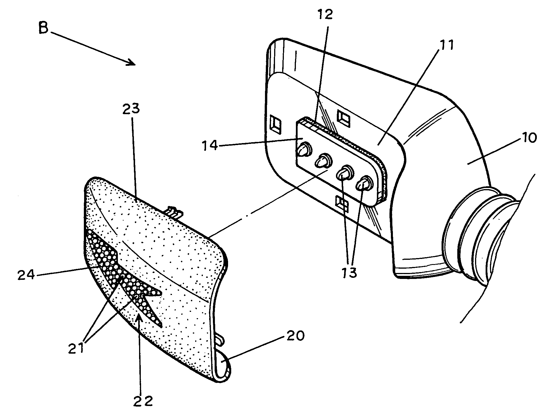
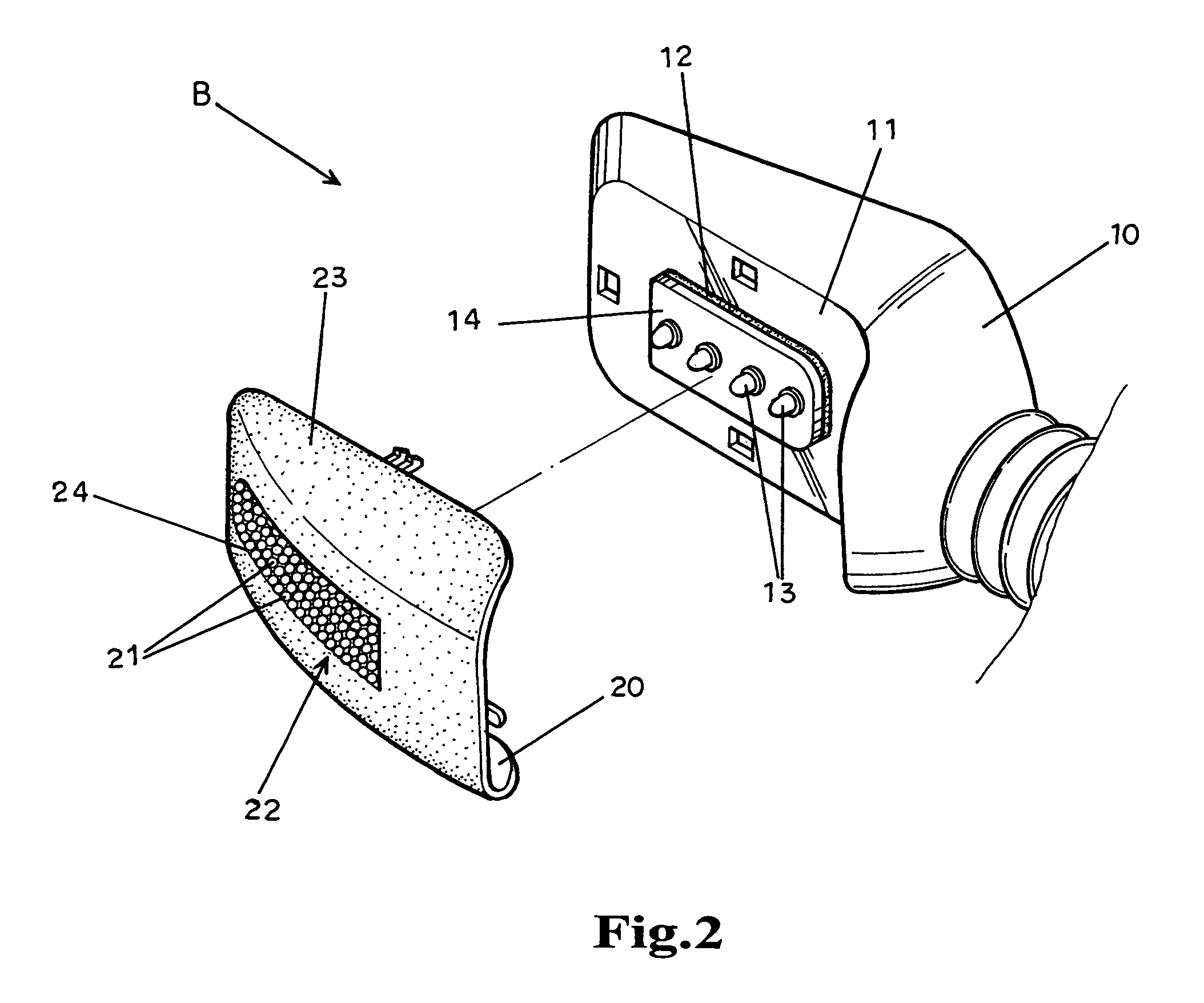
[0016]Referring to FIGS. 2 and 3, a signal light assembly B is installed in a recess 11 at the back side of an automobile's rear-view mirror 10. The signal light assembly B comprises a circuit board 14 affixed to the recess 11 by a bonding pad 12, a plurality of lamps, for example, LEDs (light emitting diodes) 13 mounted in the circuit board 14, and a lens 20 fastened to the recess 11 and covered over the circuit board 14. The circuit board 14 has an electric wire 15 extended through the rear-view mirror 10 (see FIGS. 4 and 6) and electrically connected to the power circuit of the directional signal lights of the automobile (not shown). The LEDs 13 are controlled to flash by the circuit board 14, providing a visual signal to the outside through the lens 20.

[0017]The main feature of the invention is outlined hereinafter with reference to FIG. 3. As illustrated, the lens 20 has a plurality of raised portions 21 protruded from the inner surface, forming a honeycomb-like condensing area...


PUM


Abstract

A signal light and rear-view mirror arrangement is constructed to include a circuit board mounted in the back recess of a vehicle rear-view mirror and adapted to control a set of lamps to flash, and a lens covered on the back side of the vehicle rear-view mirror, the lens having a plurality of raised portions protruded from the inner surface and forming a honeycomb-like condensing area adapted to condense and refract light from the lamps, a transparent area surrounding the honeycomb-like condensing area, and a photomask covered on the outer surface of the lens corresponding to the condensing area.

Description

BACKGROUND OF THE INVENTION[0001]1. Field of the Invention[0002]The present invention relates to a signal light and rear-view mirror arrangement and, more specifically, to technique of improving the indication of the signal light of a vehicle rear-view mirror.[0003]2. Description of the Related Art[0004]A rear-view mirror signal light assembly A is shown comprising a plurality of lamps (for example, light emitting diodes) 101 installed in a recess 102 at the back side of an automobile's rear-view mirror 100, and a lens 200 fastened to the recess 102 and covered over the lamps 101. The lamps 101 are driven to flash subject to the operation of the directional signal lamps of the motor vehicle. This design of rear-view mirror signal light assembly A is still not satisfactory in function. During flashing of the lamps 101, light from the lamps 101 is dispersed in all directions through the lens 200, weakening the indication of the signal light.SUMMARY OF THE INVENTION[0005]The present in...

Claims


Application Information

Patent Timeline
IPC IPC(8): B60R1/12
CPCB60Q1/2665B60R1/1207
Inventor HUANG, JEAN-SAN
Owner HUANG JEAN SAN
Why Eureka
Try Eureka