
Intraocular lens assembly and method

a technology of intraocular lens and assembly method, which is applied in the field of intraocular lens, can solve the problems of patient halos, inability to see halos, and inability to accommodate the majority of people,

Inactive Publication Date: 2005-08-23
KAMERLING WILLIAM +1
View PDF5 Cites 40 Cited by
  • Summary
  • Abstract
  • Description
  • Claims
  • Application Information

AI Technical Summary

Benefits of technology

[0019]Contraction of the ciliary muscle causes the optic to move anteriorly relative to the annulus and the retina so that the eye can focus on a near object.

Problems solved by technology

However, the method and device described in U.S. Pat. No. 6,282,449 is not suitable when a non-accommodating intraocular lens replaces the natural lens such as after the removal of cataracts.
However, while haptic based intraocular lenses are well known, most have not been capable of accommodation.
Thus, it is common for patient to see halos or to be annoyed by glare around the edge of the optic disc.
Further, it is relatively easy for a small optic disc to become decenterd thereby diminishing its effectiveness or making it useless.

Method used


Image

  • Intraocular lens assembly and method
  • Intraocular lens assembly and method

Examples


Embodiment Construction

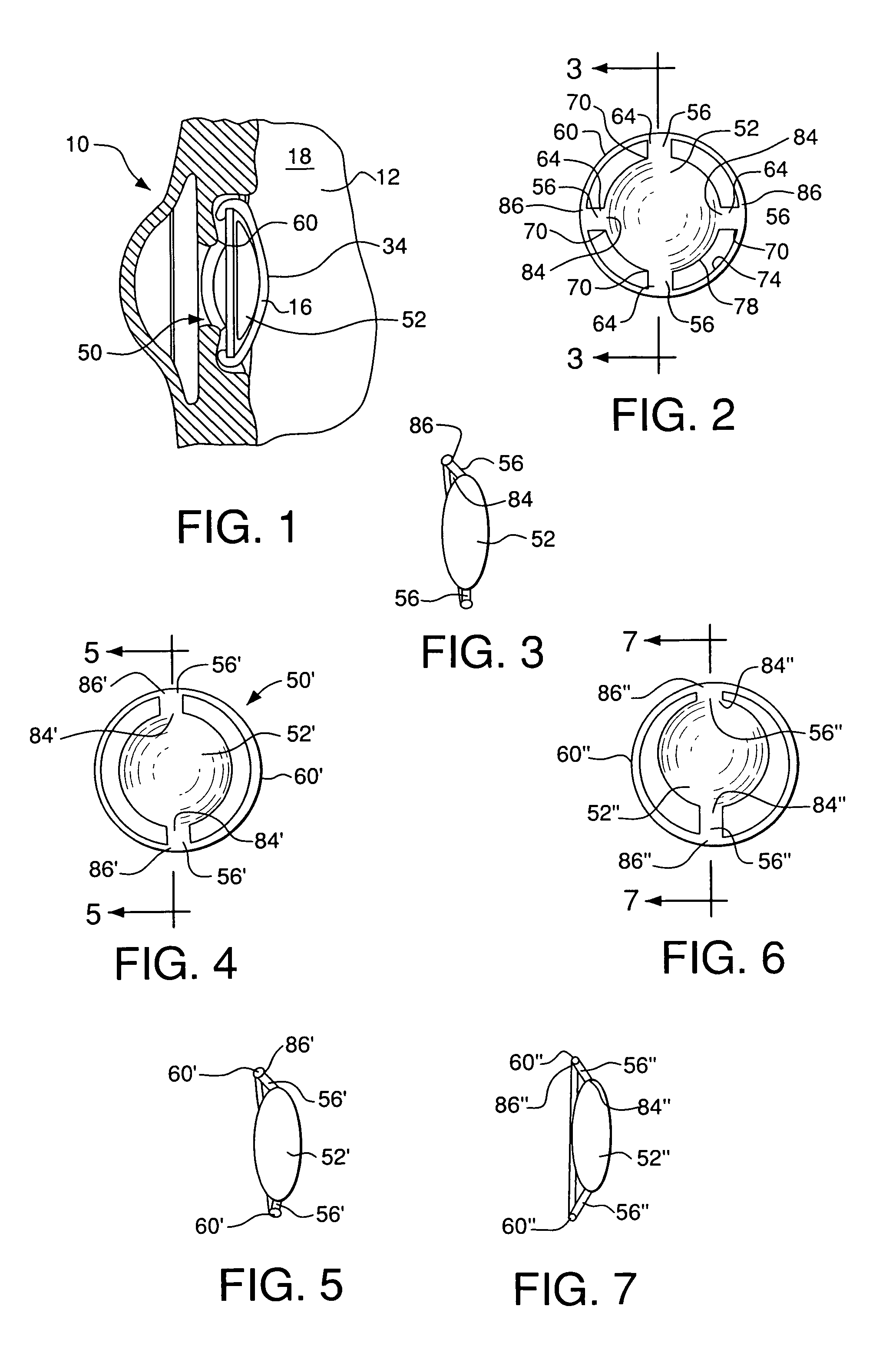
[0029]Now referring to the drawing wherein like numerals indicate like elements FIG. 1 shows a partial cross section of an eye 10.

[0030]The eye 10 includes a posterior compartment partially shown at 12. The posterior compartment 12 supports the retina at its posterior (not shown) and the lens capsule 16 at its anterior. The posterior compartment 12 carries the vitreous humor 18.

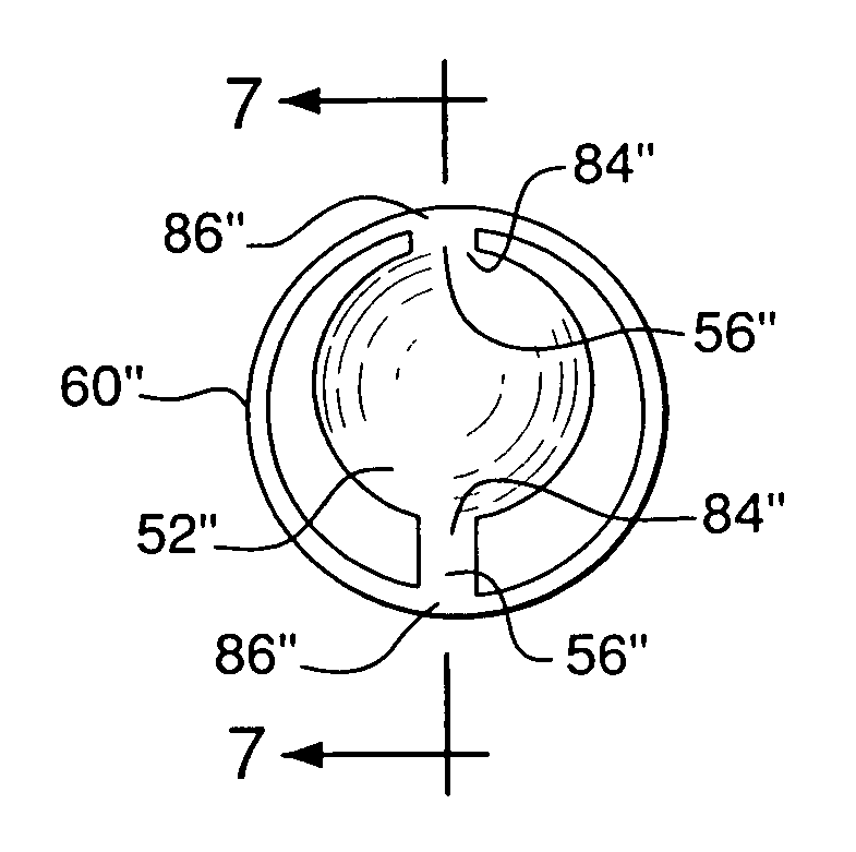
[0031]The intraocular lens assembly 50 of the invention is implanted in the posterior chamber 34 of the eye 10 after the nucleus (not shown) is removed. As best seen in FIG. 2, it includes an optic disc 52 which is connected by a plurality of hinges 56 to a haptic. The haptic is in the form of an annulus 60 which extends around the optic disc 52.

[0032]Advantageously, the optic disc 52 is about 7.00 millimeters in diameter. This has the effect of reducing the occurrence of the halos and glare that is common with optic discs of smaller diameter and assures better centration.

[0033]Further, the annulus 60 prefera...


PUM


Abstract

An intraocular lens assembly and method. The assembly comprises an optic disc and an annulus surrounding the optic disc. Hinges connect the optic disc to the annulus to permit anterior and posterior movement of the optic disc relative to the annulus in response to contraction and relaxation of the ciliary muscle so that the eye accommodates to focus on a near object. The method comprises the steps of placing in the posterior chamber an optic disc and an annulus. The annulus surrounds the optic disc and is connected to it by hinges that permit anterior and posterior movement of the optic disc relative to annulus in response to contraction and relaxation of the ciliary muscle whereby said eye accommodates to focus on a near object.

Description

FIELD OF THE INVENTION[0001]This invention relates to intraocular lenses, and more particularly, to an intraocular lens which can accommodate to permit near objects such as texts to be in focus.BACKGROUND OF THE INVENTION[0002]The subject matter of my earlier U.S. Pat. No. 4,950,290 granted on Aug. 21, 1990 and entitled POSTERIOR CHAMBER INTRAOCULAR LENS, and U.S. Pat. No. 6,282,449 granted on Aug. 28, 2001 and entitled IMPROVED METHOD AND DEVICE FOR CAUSING THE EYE TO FOCUS ON A NEAR OBJECT are incorporated in their entirety into this patent application.[0003]Typically, the eye focuses on a near object by increasing the curvature of the lens. The change in curvature is called “accommodation.” The objective of accommodation is to sharply focus an observed image on the retina.[0004]The curvature of the lens is controlled by the circular fibers of the ciliary muscle. The ciliary muscle is an annulus that is connected to the lens by the zonules. When the ciliary muscle is relaxed the l...

Claims


Application Information

Patent Timeline
IPC IPC(8): A61F2/16
CPCA61F2/1629A61F2250/0018
Inventor KAMERLING, WILLIAMKAMERLING, JOSEPH M.
Owner KAMERLING WILLIAM
Learn More