OCT (Optical Coherence Tomography) synthetic fundus image optic disc center positioning method and equipment

A center positioning and fundus mapping technology, applied in the field of positioning, can solve the problems of large calculation amount, complex algorithm, weak contrast of blood vessels and optic disc area, etc., to achieve the effect of rapid positioning analysis, fast calculation speed and strong stability

Active Publication Date: 2013-01-09
SHENZHEN CERTAINN TECH CO LTD
View PDF6 Cites 11 Cited by
  • Summary
  • Abstract
  • Description
  • Claims
  • Application Information

AI Technical Summary

Problems solved by technology

The overall quality of the optical coherence tomography (OCT) fundus composite image is not as good as that of fundus color photos, and the contrast of blood vessels and optic disc area is weak, especially the edge of the optic disc. At the same time, the scanning time of each OCT area is relatively short Long, the shaking or blinking of the human eye will affect the OCT fundus image synthesized in the later stage
Therefore, th

Method used


Image

  • OCT (Optical Coherence Tomography) synthetic fundus image optic disc center positioning method and equipment
  • OCT (Optical Coherence Tomography) synthetic fundus image optic disc center positioning method and equipment
  • OCT (Optical Coherence Tomography) synthetic fundus image optic disc center positioning method and equipment

Examples


Embodiment Construction

[0021] In order to make the object, technical solution and advantages of the present invention clearer, the present invention will be further described in detail below in conjunction with the accompanying drawings and embodiments. It should be understood that the specific embodiments described here are only used to explain the present invention, not to limit the present invention.

[0022] The above descriptions are only preferred embodiments of the present invention, and are not intended to limit the present invention. Any modifications, equivalent replacements and improvements made within the spirit and principles of the present invention should be included in the protection of the present invention. within range.

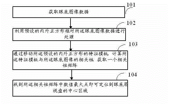
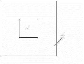
[0023] see figure 1 , figure 1 It is a schematic flowchart of a method for locating the optic disc center of an OCT synthetic fundus image provided by an embodiment of the present invention. Such as figure 1 As shown, the method for positioning the optic ...


PUM


Abstract

The invention discloses an OCT (Optical Coherence Tomography) synthetic fundus image optic disc center positioning method and equipment. The OCT synthetic fundus image optic disc center positioning method comprises the following steps of: acquiring fundus image data; processing the fundus image data by utilizing a preset inner and outer square frames; calculating the correlation between a characteristic template and the fundus image by moving the characteristic template of the preset inner and outer square frames to acquire a correlation matrix; and finding the maximum numerical value point in the correlation matrix, so that a central area of the fundus image optic disc can be positioned. Data loss or high noise is not required in the fundus image acquisition, an optic disc area acquired by standard operation of an OCT instrument generally meets the characteristics that the central area of the optic disc is dark and the periphery is bright, and the optic disc area can be rapidly and accurately positioned; and therefore, the algorithm is higher in stability and higher in calculation speed and can be used for rapidly positioning and analyzing a lots of fundus images.

Description

technical field [0001] The invention belongs to the technical field of positioning, and in particular relates to a method and equipment for positioning the center of an optic disc of an OCT synthetic fundus image. Background technique [0002] The current optic disc center positioning technology of fundus map mainly includes: 1. Positioning of the optic disc center based on the blood vessels in the fundus map, and positioning of the optic disc center based on the direction of the blood vessels; 2. Positioning of the optic disc area based on hough circle detection and active contour model. [0003] First, both methods are based on edge features of images, such as blood vessels and optic disc edges. However, edge detection is greatly affected by image quality, so at present, these two aspects mainly focus on non-OCT-synthesized fundus maps, such as fundus maps obtained by fundus cameras. Because the image quality of this type of fundus map is clear, blood vessels and optic di...

Claims


Application Information

Patent Timeline
IPC IPC(8): A61B3/12A61B3/14
Inventor 洪文佳
Owner SHENZHEN CERTAINN TECH CO LTD
Why Eureka
Try Eureka