Method for sampling optic disc data and apparatus thereof

a technology of optic discs and optic discs, which is applied in the direction of digital signal error detection/correction, instruments, recording signal processing, etc., can solve the problems of continuous accumulation of timing errors of signals, easy scratching of optic discs, so as to improve accuracy and reliability of data reading from optic discs. , the effect of accurately sampling the data read

Active Publication Date: 2005-11-10
TIAN HLDG
View PDF3 Cites 12 Cited by
  • Summary
  • Abstract
  • Description
  • Claims
  • Application Information

AI Technical Summary

Benefits of technology

[0014] In order to avoid the disadvantages in the prior art, the present invention provides a method for sampling optic disc data. The method can accurately sample the data read from the optic disc's defective area caused by a scratch or other reason. As a result, the accuracy and the reliability of data reading from an optic disc are improved.

Problems solved by technology

However, errors occur in the timing of the physical data sampling tag signal “DataTag_N”, and the errors may be a lead or a lag error.
As the reading data “Data” is increasing, the timing error of the data sampling tag signal “DataTag_N” gradually accumulates, which causes an error on the result of the dividing and sampling of the data signal DSEFM.
However, it is well known that the optic disc which is a round plate make of a plastic material is easily scratched.
After comparing the data sampling tag signal “DataTag_N” generated under a normal situation with the data sampling tag signal “DataTag_W” which is not accurately tuned in time, it is known that the timing error of the signal “Bw” is continuously accumulated due to the fact that the signal “STb” does not appeared in time.
When reading the defective area caused by a scratch or other reason, usually it is not possible to generate the sync tag signal “SyncTag” at the right time.

Method used


Image

  • Method for sampling optic disc data and apparatus thereof
  • Method for sampling optic disc data and apparatus thereof
  • Method for sampling optic disc data and apparatus thereof

Examples


Embodiment Construction

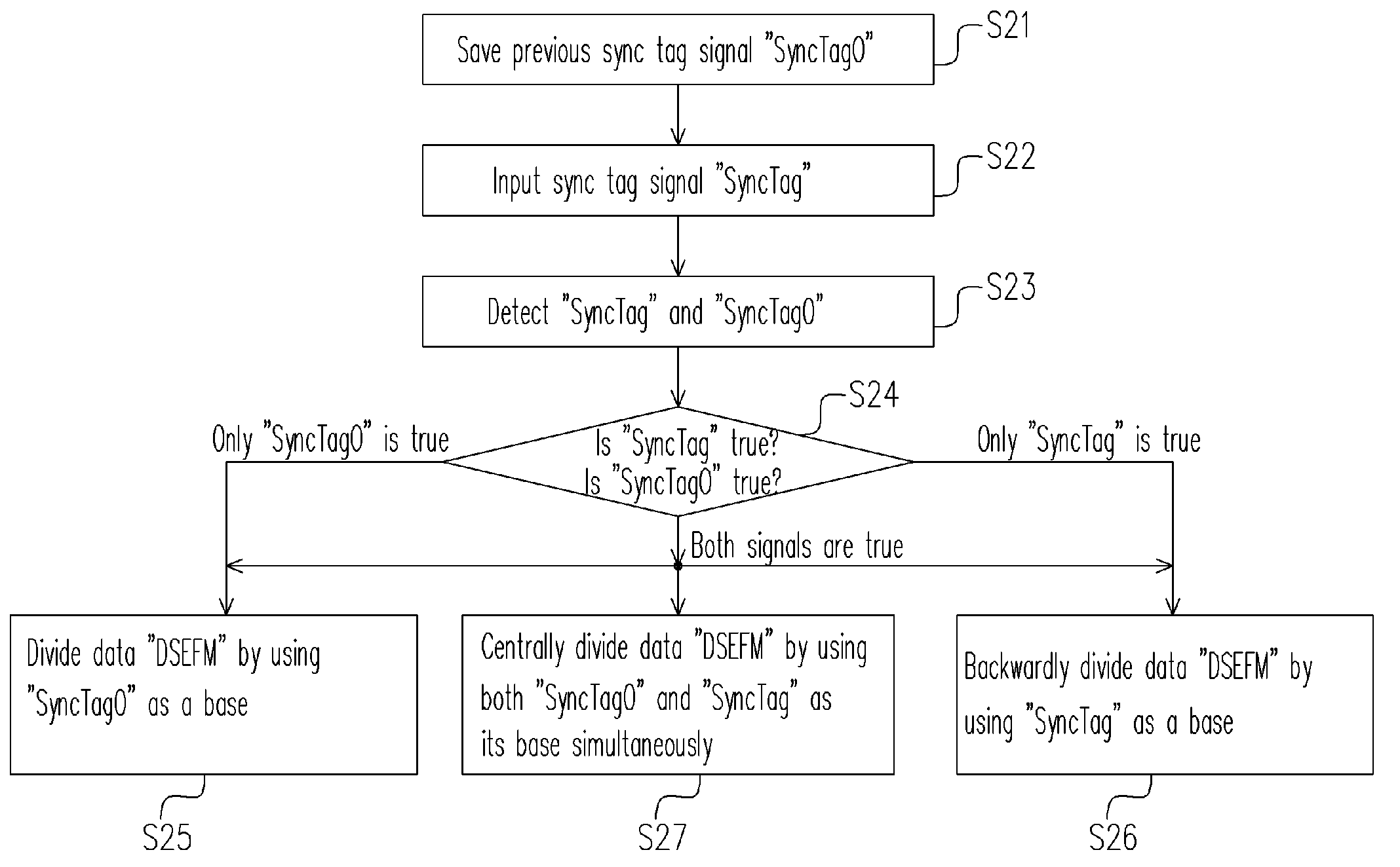
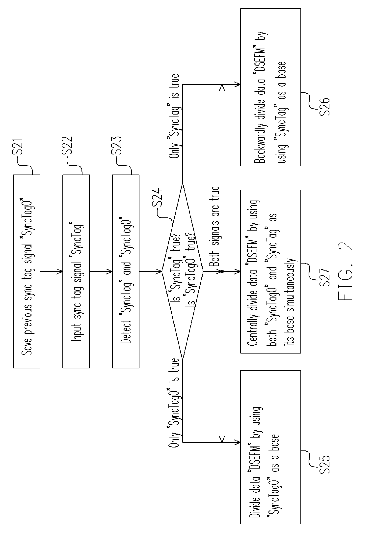
[0029] To facilitate the explanation of the present invention and each embodiment, the so-called “backwardly” refers to the timing is counted from a certain base to a past time, and the so-called “forwardly” refers the timing is counted from a certain base to a future time hereinafter.

[0030]FIG. 2 is a flow chart illustrating a method for sampling optic disc data according to an embodiment of the present invention. Referring to FIG. 2, a sync tag signal “SyncTagO” appeared in the previous time is saved in step S21. Then both the sync tag signal “SyncTag” and the data signal “DSEFM” most recently appeared are received in step S22, wherein, the sync tag signal “SyncTagO” and the sync tag signal “SyncTag” are two signals appeared contiguously. The sync tag signal “SyncTagO” and the sync tag signal “SyncTag” are further detected in step S23, and step S24 is performed after the detection is completed. The true-false relation of these two signals mentioned above is determined in step S24...


PUM

PropertyMeasurementUnit
data lengthaaaaaaaaaa
lengthaaaaaaaaaa
timeaaaaaaaaaa

Abstract

The present invention discloses a method for sampling optic disc data. The method includes the following steps. First, a first sync tag signal and a data signal are provided, and the previous first sync tag signal is saved as a second sync tag signal. Then, it is checked and determined whether the value of the first sync tag signal and the second sync tag signal is true or false so as to divide the data signal. Since the neighboring sync tag signals are detected simultaneously, and the timing for sampling the data in the frame is determined according to whether the two contiguous sync tag signals are true or false, the present invention can improve the disadvantages of the prior art.

Description

CROSS-REFERENCE TO RELATED APPLICATION [0001] This application claims the priority benefit of Taiwan application serial no. 93110814, filed on Apr. 19, 2004. All disclosure of the Taiwan application is incorporated herein by reference. BACKGROUND OF THE INVENTION [0002] 1. Field of the Invention [0003] The present invention relates to a method for reading optic disc data, and more particularly, to a method for sampling optic disc data. [0004] 2. Description of the Related Art [0005] Among different types of storage media, the optic disc is commonly used in various fields due to its characteristic of high capacity, low cost, and convenience in carrying. It is applied in storing data, listening music, and watching movies. In order to adapt to the characteristic of optic disc and to increase the reliability of the optic disc data reading, during the data is being stored into the optic disc, the current burning status in optic disc is changed when the data value is 1, and the current bu...

Claims


Application Information

Patent Timeline
Patent Type & Authority Applications(United States)
IPC IPC(8): G11B7/005G11B20/14G11C5/00
CPCG11B7/0053G11B2220/2537G11B27/3027G11B20/1403
Inventor OUYANG, SLLAI, YI-LINHU, PEI-JEI
Owner TIAN HLDG
Why Eureka
Try Eureka