
Brushless direct current monophase motor drive circuit

a direct current monophase, motor technology, applied in the direction of motor/generator/converter stopper, dynamo-electric converter control, electronic commutator, etc., can solve the problem of destroying electronic components by heat, reducing the lifetime of the motor, and generating a large amount of heat from fet q2/b>, so as to shorten the motor life and reduce the heat generation

Inactive Publication Date: 2005-08-23
MINEBEAMITSUMI INC
View PDF9 Cites 7 Cited by
  • Summary
  • Abstract
  • Description
  • Claims
  • Application Information

AI Technical Summary

Benefits of technology

[0027]The present invention was conceived to solve the problems of the prior art described above and its object is to provide a brushless direct current monophase motor drive circuit that can decrease the heat generation from the switching elements on the power source side, perform absorption of the cur

Problems solved by technology

There is a concern that the heat generated from the above-mentioned electronic components is confined in the housing and destroys the electronic components by heat.
However, the problem associated with this occurrence was that a great amount of heat was generated from FET Q2 (or Q1), especially from its parasite diode.
Each electrolytic capacitor EC constituting the electrolytic capacitor group 31 has a short lifetime compared to other components, and failures are easily provoked.
There was an additional problem that, compared to other components, the electrolytic capacitors EC occupy a large space on the component mounting printed board (not shown).
Therefore, in order to increase the efficiency of heat dissipation, radiators, or fan motors, for example, had to be mounted increasing the cost significantly.

Method used


Image

  • Brushless direct current monophase motor drive circuit
  • Brushless direct current monophase motor drive circuit
  • Brushless direct current monophase motor drive circuit

Examples


Embodiment Construction

[0033]In the following, embodiments of the invention will be described with reference to the drawings.

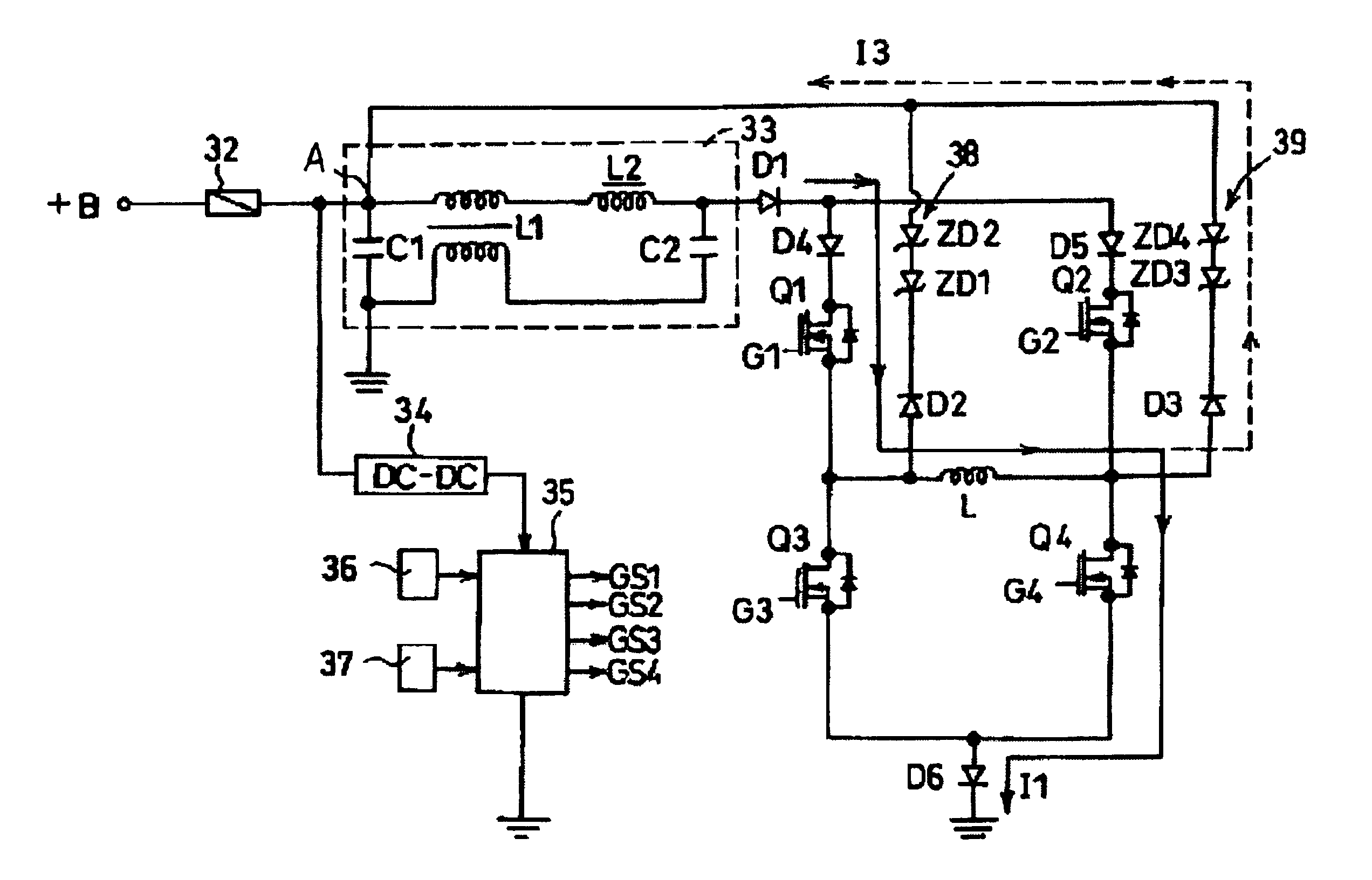
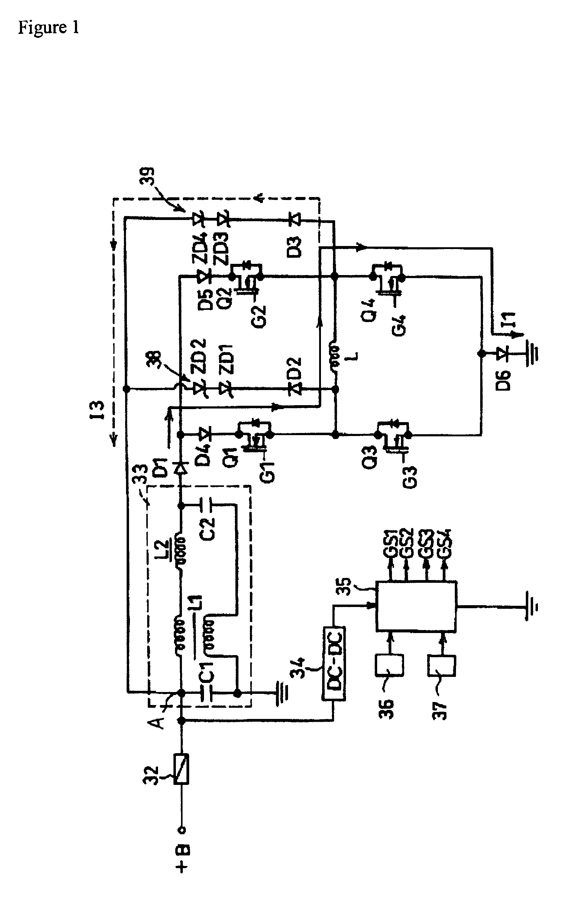
[0034]One embodiment of the brushless direct current monophase motor drive circuit according to the present invention is shown in FIG. 1.

[0035]In this figure, +B represents the direct current power source to drive a brushless direct current monophasic motor coil (motor coil) L.

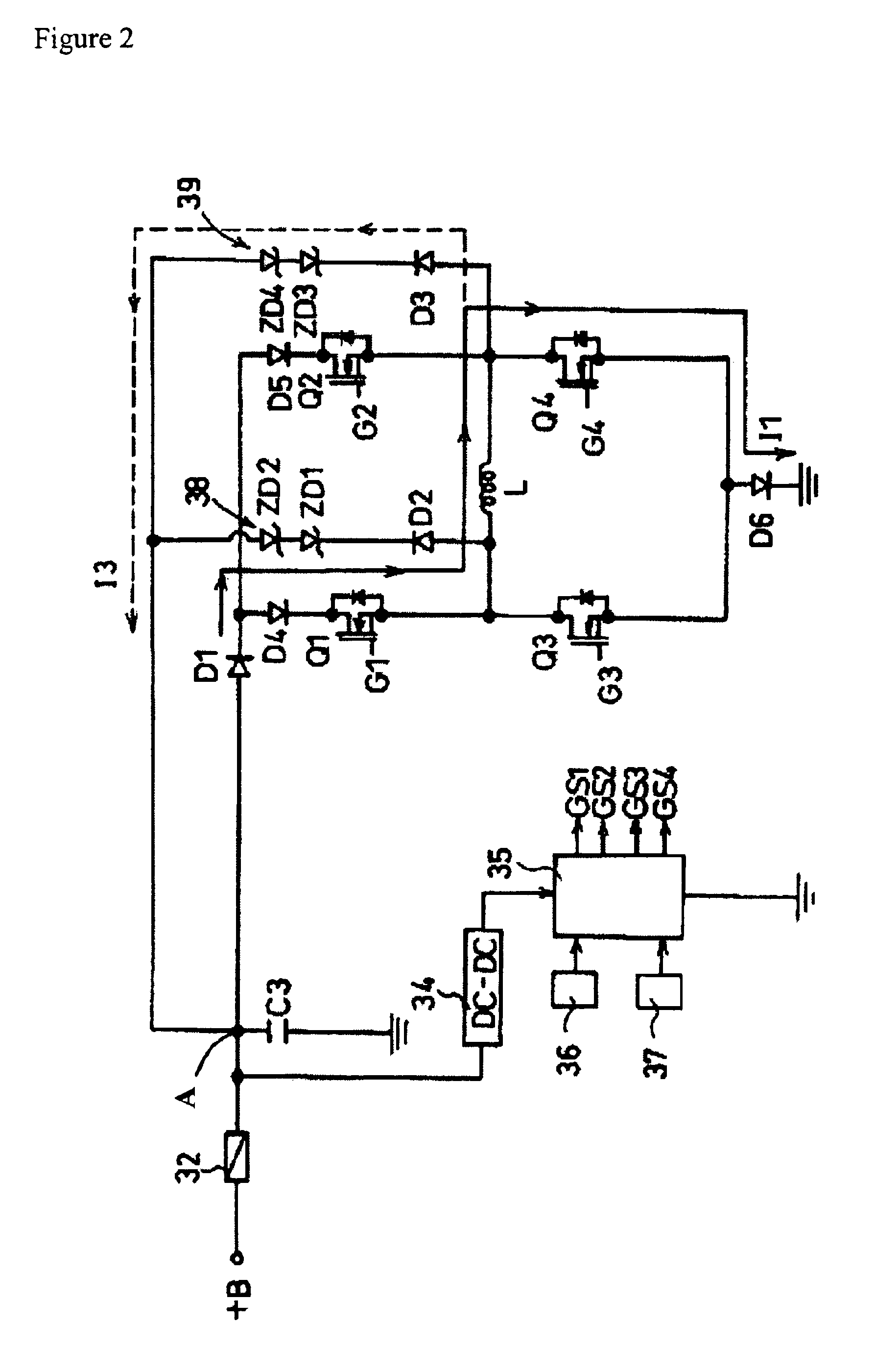
[0036]The drive circuit is constituted by mounting 4 switching elements, here, MOS type power FETs (field-effect transistors) Q1-Q4, diodes D1, D4, and D5 for reverse current prevention, a diode D6 for reverse connection (power source reverse polarity connection) protection, and current back flow electrical paths 38 and 39.

[0037]In this case, the MOS type power FETs Q1-Q4 can be divided into 2 sets of serially connected switching element assemblies (a first serially connected assembly consisting of FETs Q1 and Q4, and a second serially connected assembly consisting of FETs Q2 and Q3), each one being connected ...


PUM


Abstract

A brushless direct current motor drive circuit having a serially connected motor coil energizing circuit, a serially connected feedback circuit, a pre-drive circuit, a position sensor, and a duty ratio controller. This circuit can decrease the heat generation from the switching elements on the power source side, perform absorption of the current flowing back in the direction of the switching elements on the power source side when the duty ratio is set to less than 100% without using an electrolytic capacitor group that causes a shortening of the motor lifetime, and solve various problems caused by the use of an electrolytic capacitor group.

Description

CROSS-REFERENCE TO RELATED APPLICATIONS[0001]This application claims all rights of priority to Japanese Patent Application No. 2002-149204 (pending).BACKGROUND OF THE INVENTION[0002]1. Field of the Invention[0003]The present invention relates to a brushless direct current monophasic motor, and more particularly to a drive circuit thereof.[0004]2. Description of the Related Art[0005]In office automation equipment such as personal computers or photocopiers, a number of electronic devices have electronic components, which are contained in a relatively narrow housing. There is a concern that the heat generated from the above-mentioned electronic components is confined in the housing and destroys the electronic components by heat. Therefore, air vents are made and a fan motor is mounted to the air vent to evacuate the heat from inside the housing to the outside.[0006]For this purpose, it is not uncommon to use a brushless direct current monophase motor. FIG. 3 describes a drive circuit o...

Claims


Application Information

Patent Timeline
IPC IPC(8): H02P6/08H02P6/00H02M7/48H02M7/5387H02P6/06H02P6/12H02P6/26
CPCH02P6/008H02P6/085H02P6/26
Inventor JUNNAN, XIKONNO, MITSUO
Owner MINEBEAMITSUMI INC
Learn More