FET current regulation of LEDs

Inactive Publication Date: 2005-08-23
FIBER OPTIC DESIGNS +1
View PDF4 Cites 53 Cited by
  • Summary
  • Abstract
  • Description
  • Claims
  • Application Information

AI Technical Summary

Benefits of technology

[0011]The present invention uses Field Effect Transistors (FETs) to regulate LED current. FETs are fundamentally voltage driven devices, where output current is governed by junction volta

Problems solved by technology

Real diodes have complicated internal behavior and, of course, finite current.
While this “direct drive” approach is simple, in

Method used


Image

  • FET current regulation of LEDs
  • FET current regulation of LEDs
  • FET current regulation of LEDs

Examples


Embodiment Construction

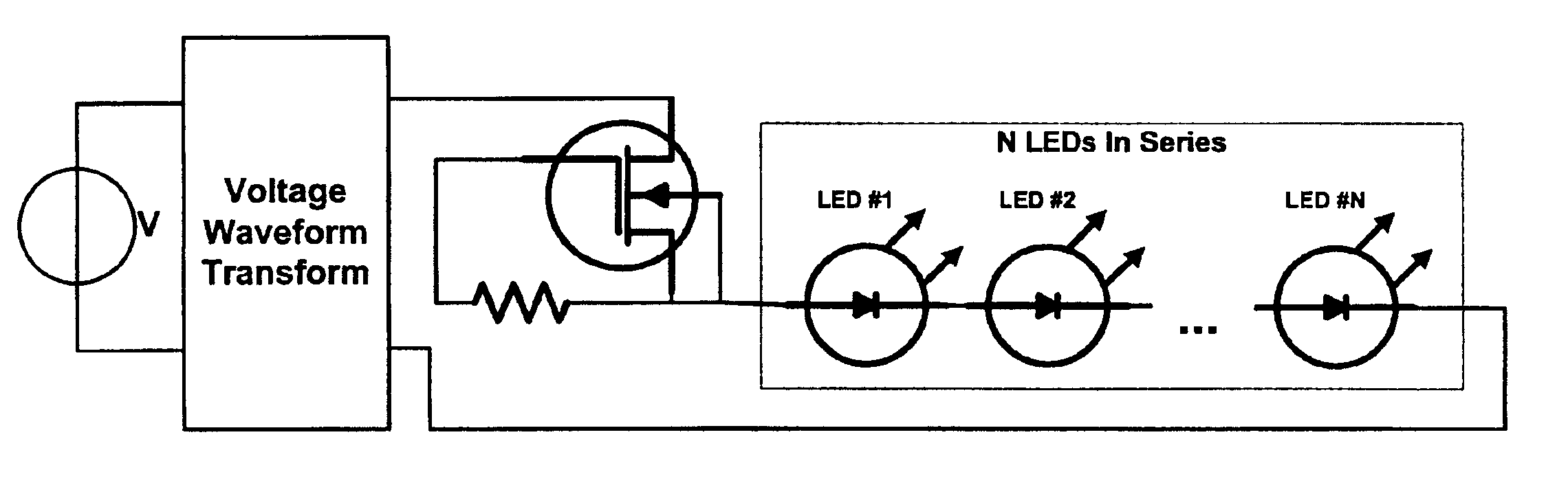
to LED Light String” which is hereby incorporated by reference, that by matching waveform-dependent LED voltages to the stable source voltage, LED current can remain operationally stable without current limiting circuitry. While this “direct drive” approach is simple, inexpensive and electrically efficient, with no added power loss, there are also several drawbacks to this “direct drive” method.

[0006]One drawback to “direct drive” of LEDs is that the method of voltage matching requires a stable source voltage—this can often be met with AC line voltage (e.g., 120 VAC) but it may difficult to meet with batteries having large voltage droop. A second drawback to “direct drive” is inherent sensitivity to voltage variations. These voltage variations are of two primary types: source and device. An example of source voltage variation is difference in line voltage between, say, a place in California versus a place in Pennsylvania, where the latter often is several volts closer to the nominal...


PUM


Abstract

Field Effect Transistors (FETs) are used to regulate current in a light emitting diode (LED). FETs are fundamentally voltage driven devices, where output current is governed by junction voltage. Since junction voltage can be controlled with little or no support circuitry, FETs present a solution to current regulation where cost, complexity, and perhaps even size are important.

Description

[0001]This non-provisional application claims the benefit of U.S. Provisional Patent Application No. 60 / 391,670 filed Jun. 27, 2002.FIELD OF THE INVENTION[0002]The invention relates to a system for current regulation of light emitting diodes using field effect transistors.BACKGROUND OF THE INVENTION[0003]Under analysis is a plurality of Light Emitting Diodes (LEDs) as shown in FIG. 1. With reference to FIG. 1, the voltage source may first undergo a voltage waveform transformation (e.g., AC to DC) before driving multiple series blocks of LEDs, where the M series blocks are connected together in parallel. Each of the M series blocks may have circuitry to control current. For conceptual convenience only a single series block of N LEDs is referred to throughout.[0004]Diodes are well known in electrical engineering to be “current-driven” devices. In practice “current-driven” means that a large change in device current is produced by a small change in applied voltage. An ideal diode descr...

Claims


Application Information

Patent Timeline
IPC IPC(8): G05F1/40G05F1/10H01S3/13H05B37/02
CPCH05B33/0809H05B33/0812Y02B20/345H05B45/395Y02B20/30H05B45/46
Inventor ALLEN, MARK R.
Owner FIBER OPTIC DESIGNS
Why Eureka
Try Eureka