High efficiency viewing screen

a viewing screen, high-efficiency technology, applied in the field of viewing screens, can solve the problems of high retroreflectance, unsuitable use, and exhibiting one or more deleterious effects, and achieve the effect of improving daylight readability

Active Publication Date: 2005-08-23
HONEYWELL INT INC
View PDF56 Cites 97 Cited by
  • Summary
  • Abstract
  • Description
  • Claims
  • Application Information

AI Technical Summary

Benefits of technology

[0031]One embodiment of the present invention employs a volume diffuser in combination with several other components to provide a high resolution, low cost, high transmittance screen. The other combinations of components, collectively referred to herein as an “optical stack,” act to, among other things, provide high ambient light rejection. The overall combination provides quality attributes desired in a viewing screen.
[0033]In a preferred embodiment, the present invention provides a viewing screen having high transmittance of polarized light from an LCD, while maintaining high ambient light rejection through the use of a polarizer, a volume diffuser, and optical coupling to eliminate fresnel reflections. It is noted that a significant aspect of the present invention is that the achieved high efficiency is a result of, at least in part, the use of a diffuser that exhibits minimal birefringence. Further, an antireflection means on the output surface is employed (e.g. thin film interference coating, motheye feature), specifically avoiding textured antiglare surface treatments, which only serve to worsen diffuse reflectance.
[0035]The non-birefringent diffuser receives information-coded, collimated, polarized light from the display, and increases the divergence to meet the viewing angle requirements of a given application. This light of greater divergence is further passed through a polarizer, which acts to reject ambient light in the viewer's environment. The non-birefringent properties of such a diffuser gives rise to high optical throughput, and excellent uniformity. In a preferred embodiment, the screen is index-coupled from input to output to reduce fresnel reflections, improving both throughput and ambient light rejection.
[0043]“. . . In accordance with one aspect of the present invention, the constraint on lateral scattering is relaxed by using a diffuser in which the laterally scattered light is preferentially depolarized and absorbed by the polarizing element of the screen assembly. Relaxing this constraint allows a thicker diffuser to be used. Accordingly, a screen that has a high resolution (MD) can be constructed which also has low color and speckle. By purposefully allowing a significant portion of depolarizing lateral scattering, it is easier to select a formulation at least as thick as the threshold thickness. When the diffusing element, which otherwise substantially preserves polarization of the diffused light, is combined with an absorbing polarizer, it can be used as a rear projection screen to display a high-resolution, artifact-free projected polarized image.”

Problems solved by technology

In laboratory testing of a device in accordance with the '198 patent, it has been observed that existing screen technology (e.g. black-matrix beaded-screens and engineered surface-diffusers), was not suitable for use in this application, exhibiting one or more deleterious effects, such as high absorption, high ambient light reflectance, high retroreflectance, “noisy” imagery, etc.

Method used


Image

  • High efficiency viewing screen
  • High efficiency viewing screen
  • High efficiency viewing screen

Examples


Embodiment Construction

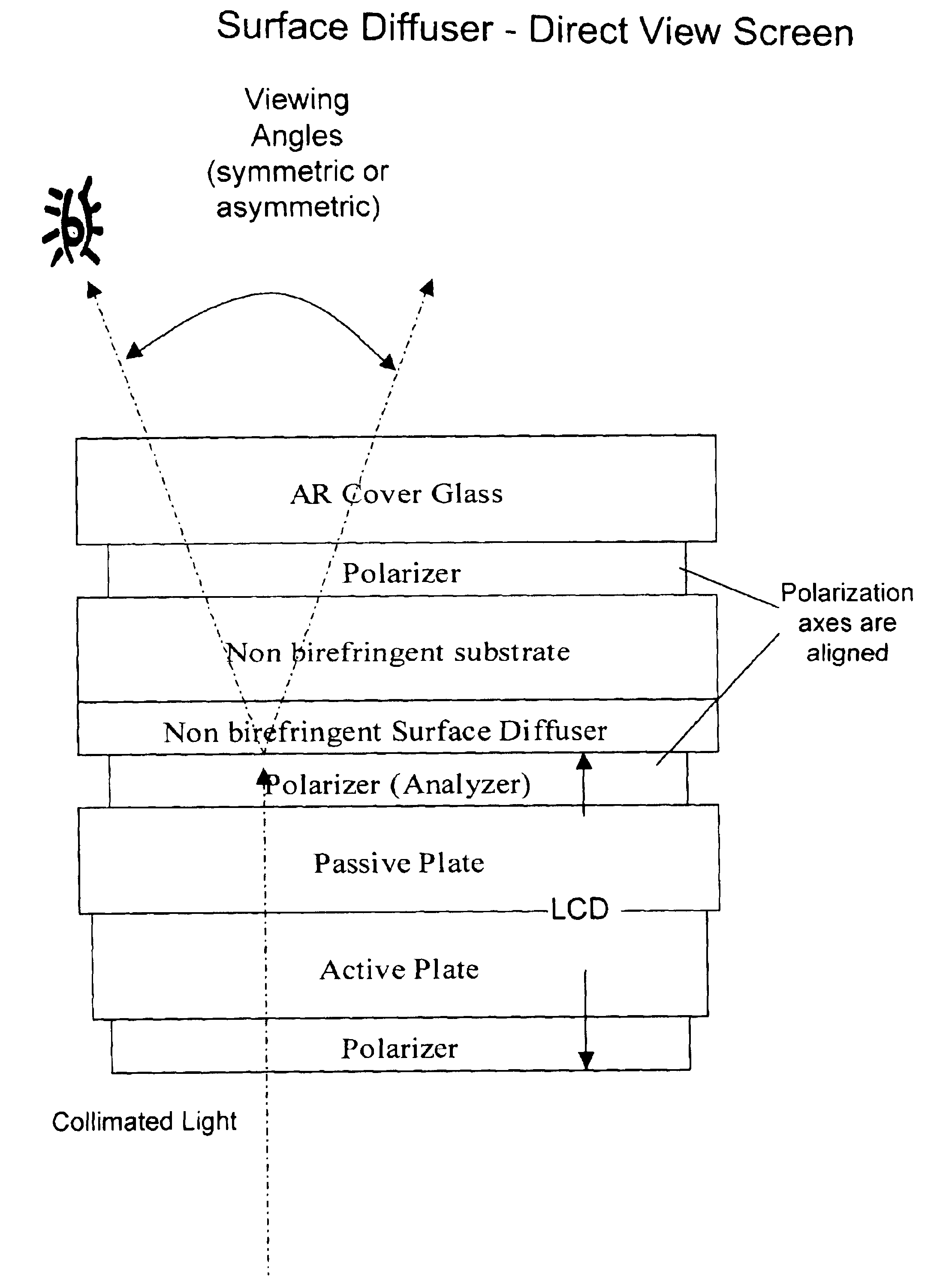
[0065]One embodiment of the present invention, shown in FIG. 1, was realized using a surface diffuser, like that described in U.S. Pat. Nos. 6,010,747 and 6,261,664, and manufactured by Wavefront Technology (Paramount, Calif.).

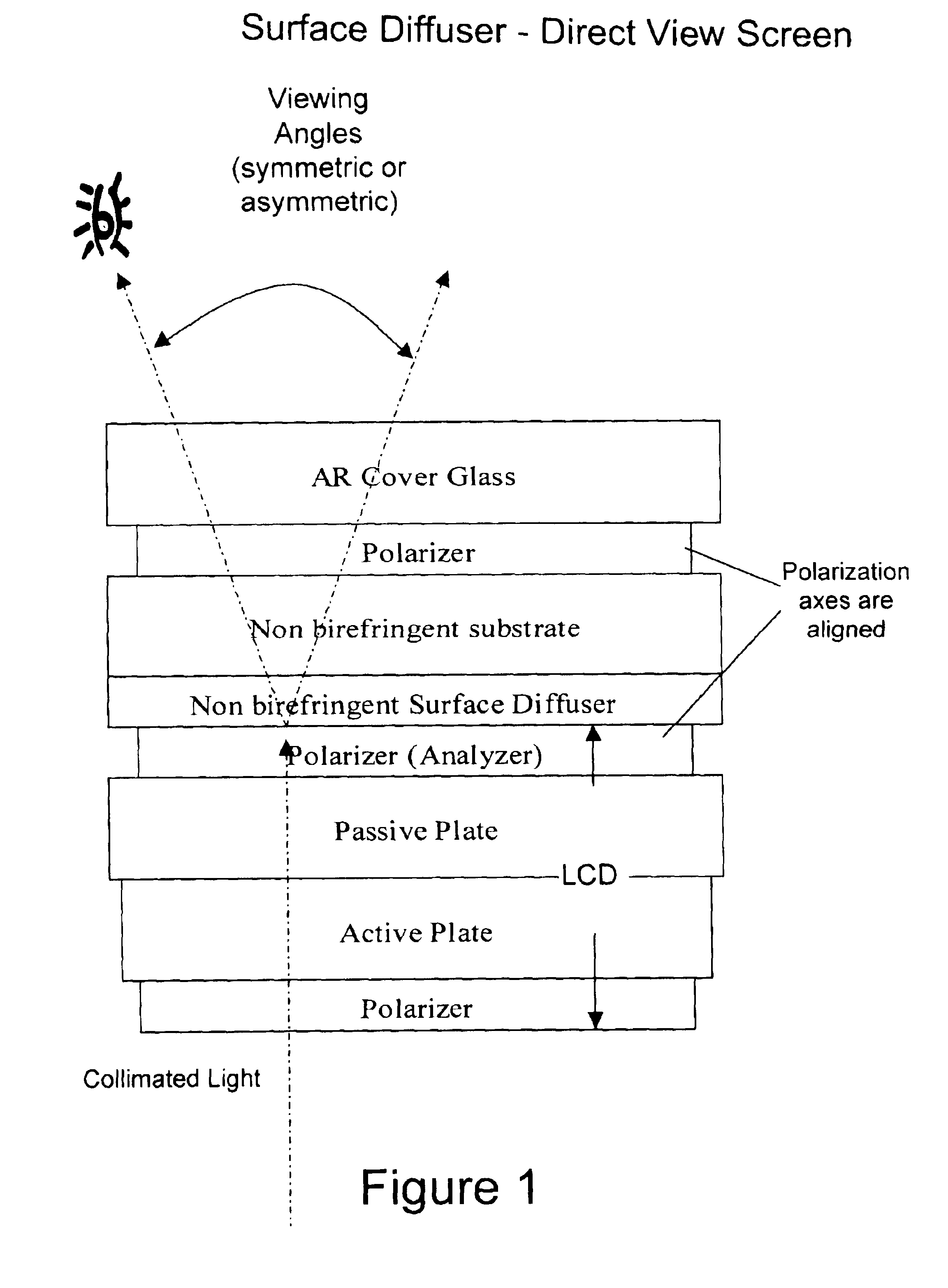
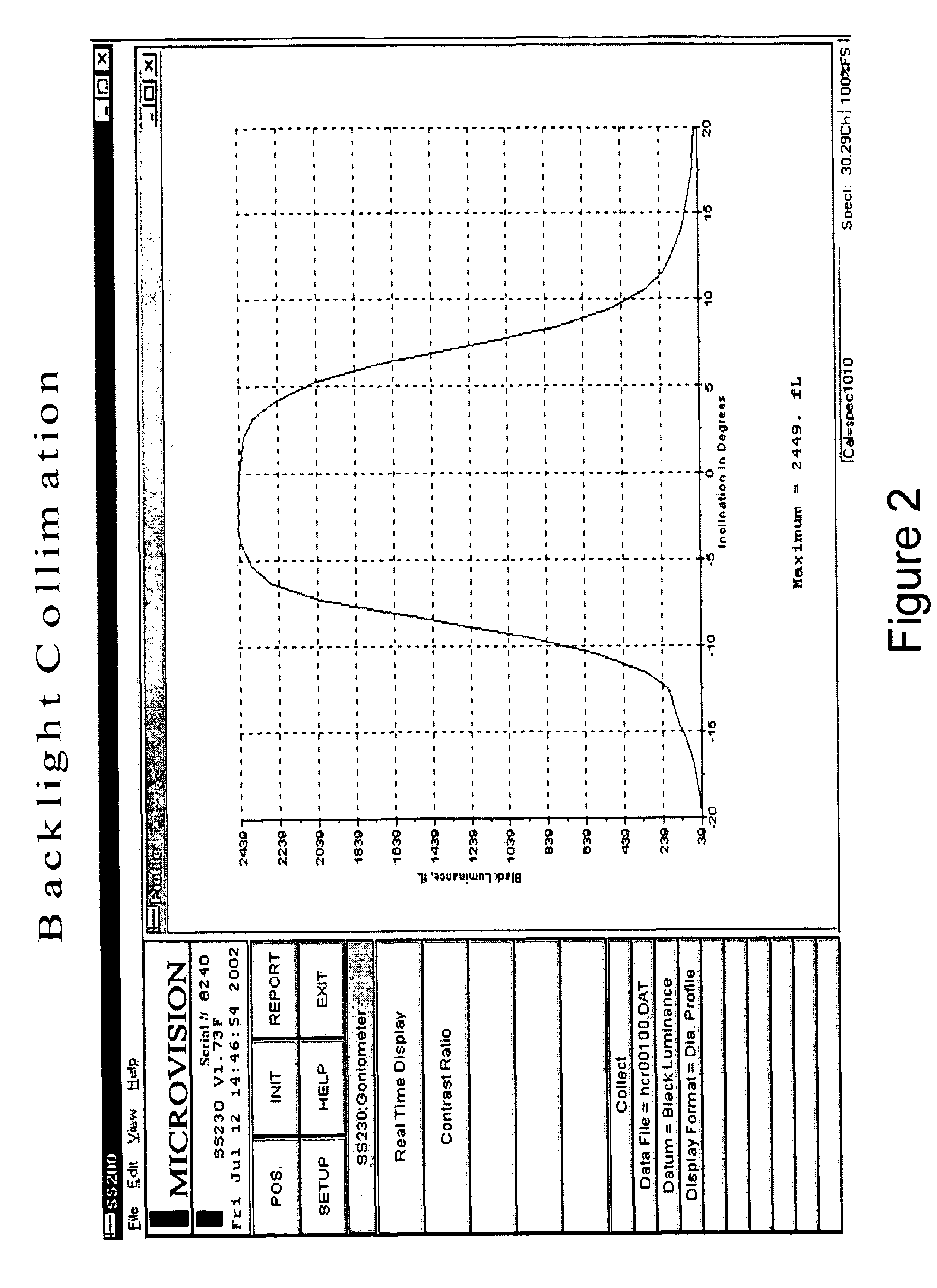
[0066]When used as a direct view screen as shown in FIG. 1 (without the polarizer and AR cover glass), the results were unimpressive in terms of luminance and contrast in ambient lighting. The test setup included the 10.4″ XGA resolution LCD in combination with the collimation structure shown in FIGS. 9 & 13 of U.S. Pat. No. 6,428,198, referenced earlier. The fibers used are ESKA 1.5 mm diameter, and the light source was a commercial off the shelf Wavien fiber optic illuminator. The resultant collimation incident on the LCD is shown in FIG. 2. A subsequent review of the diffuser using a Fourier scope revealed significant birefringence, thought to be mainly due to the film substrate. When the same diffuser was cast on a low birefringence substrate (cast acrylic...


PUM

PropertyMeasurementUnit
thicknessaaaaaaaaaa
diameteraaaaaaaaaa
reflectanceaaaaaaaaaa

Abstract

A low-scatter polarization-preserving multilayer viewing screen. A substrate D, preferably a volume diffuser, for increasing the divergence of information-coded-light while preserving its polarization sense A as it passes therethrough has a discrimination of at least 2:1 within a viewing zone. An absorbing polarizer on one or both sides of D and aligned to pass polarization state A. In one embodiment, there is provided a polarization-state phase-shift layer for modifying the polarization state of forward-scatter and / or back-scatter that total internally reflects within the viewing screen into the state opposite of A. The phase-shift layer being located at any position between the polarizer and an outermost surface of the viewing screen through which said information-coded light passes.

Description

[0001]This application claims the benefit of U.S. Provisional Application No. 60 / 411,863, filed Sep. 20, 2002, and U.S. Provisional Application No. 60 / 470,233, filed May 14, 2003, which are both incorporated herein by reference in their entirety.BACKGROUND[0002]1. Field of the Invention[0003]The present invention is directed to viewing screens, sometimes referred to as projection-screens, imaging-screens, or diffusion-screens. More particularly, the present invention is directed to a viewing screen having high resolution, low cost, high transmittance, low retroreflection effects, and high ambient light rejection.[0004]2. Background of the Invention[0005]A brief summary of screen technologies is set forth below.[0006]Buchner (U.S. Pat. No. 997,899 and U.S. Pat. No. 1,666,808) describes daylight projection screens based on lenticular elements along with an overall absorbing filter for enhanced daylight readability.[0007]Shimizu (U.S. Pat. No. 1,942,841) describes a lenticular screen w...

Claims


Application Information

Patent Timeline
Patent Type & Authority Patents(United States)
IPC IPC(8): G02B5/02G02F1/1335G03B21/56
CPCG02B5/0242G02B5/0278G02B5/0284G03B21/56G03B21/00G02B5/02G02B13/20B82Y20/00
Inventor SACCOMANNO, ROBERT J.LU, KANGHUA
Owner HONEYWELL INT INC
Why Eureka
Try Eureka