Eureka AIR delivers breakthrough ideas for toughest innovation challenges, trusted by R&D personnel around the world.

Image heating device, image forming apparatus, image copying machine, and method for controlling temperature

a technology of heating device and heating device, which is applied in the direction of electrographic process apparatus, instruments, optics, etc., can solve the problems of fixing failure, fixing failure, and temperature of pressure roller not sufficiently high,

Inactive Publication Date: 2005-08-23
PANASONIC CORP
View PDF24 Cites 1 Cited by
  • Summary
  • Abstract
  • Description
  • Claims
  • Application Information

AI Technical Summary

Benefits of technology

[0013]With the foregoing configuration of the image heating device, the decrease in glossiness at both ends of the material to be heated in the axial direction of the pressing means (pressure roller) can be prevented.
[0016]In the case where the thermal capacity of the belt is set to be not more than 60 J / K, it is estimated that the heating of the belt by the heat-generating means with an applied electric power of 1000 W causes only one tenth or less of the belt to be heated actually in a static state, thereby raising the temperature of the belt up to 200° C. or above within a short time of approximately one second. Furthermore, in the case where the thermal capacity of the belt is set to be not more than 40 J / K, the heating of the belt by the heat-generating means with an applied electric power of 900 W raises the temperature of the belt up to several hundreds of degrees Celsius or above within a short time of approximately one second.
[0018]With the foregoing configuration, the decrease in glossiness at both ends of the material to be heated in the axial direction of the pressing means can be prevented also in the case where a new print request is issued within a predetermined period after the completion of printing.
[0020]This configuration makes the detected temperature of the belt coincide with the ambient temperature, thereby preventing the temperature of the pressure roller from rising to above the temperature of the belt. Thus, it is possible to estimate the temperature of the pressure roller appropriately.
[0022]According to this configuration, the decrease in glossiness occurring from the leading end toward the trailing end of the material to be heated in the feed direction can be prevented.
[0028]As described above, by selecting an optimal look-up table based on the degree of the cooling of the belt, the temperature of the pressure roller can be estimated from the temperature or a variation in the temperature of the belt without providing a temperature sensor for the pressure roller, thereby making it possible to set an optimal fixing temperature.

Problems solved by technology

Accordingly, in an early stage of the device operation, the temperature of the pressure roller is not sufficiently high while the belt already has reached a fixing temperature.
Consequently, glossiness decreases from the leading end toward the trailing end of the recording medium in the direction in which the recording medium is fed (hereinafter, referred to as “feed direction”), resulting in fixing failure in the worst case (irregularity in gloss in the feed direction).
Thus, glossiness decreases at both ends of the recording medium in the axial direction of the heat-generating roller, resulting in fixing failure in the worst case (irregularity in gloss in the axial direction).

Method used


Image

  • Image heating device, image forming apparatus, image copying machine, and method for controlling temperature
  • Image heating device, image forming apparatus, image copying machine, and method for controlling temperature
  • Image heating device, image forming apparatus, image copying machine, and method for controlling temperature

Examples


first embodiment

(First Embodiment)

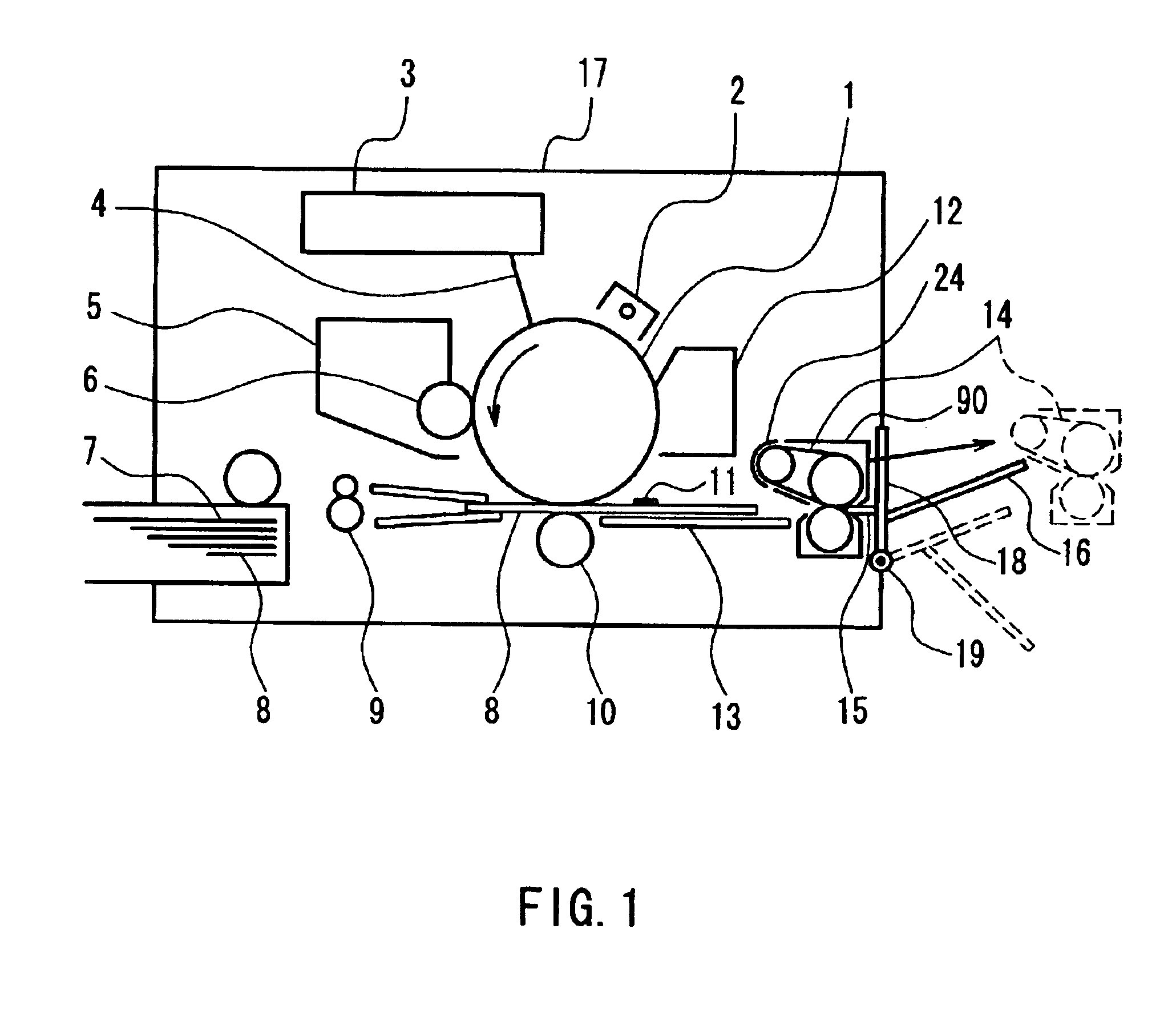
[0058]FIG. 1 is a schematic cross-sectional view showing an overall configuration of an image forming apparatus using as a fixing device an image heating device according to a first embodiment of the present invention. The configuration and operation of this apparatus will be described in the following.

[0059]In FIG. 1, numeral 17 denotes an outer shell for the main body of the image forming apparatus, and numeral 1 denotes an electrophotographic photoreceptor (hereinafter referred to as “photosensitive drum”). While this photosensitive drum 1 is rotationally driven at a predetermined peripheral speed in the arrow direction, its surface is charged homogeneously to a predetermined negative dark potential V0 by a charger 2.

[0060]Numeral 3 denotes a laser beam scanner, which outputs a laser beam 4 that is modulated in accordance with a time-series electric digital image signal of image information that is input from a host device (not shown in the drawing) such as an i...

second embodiment

(Second Embodiment)

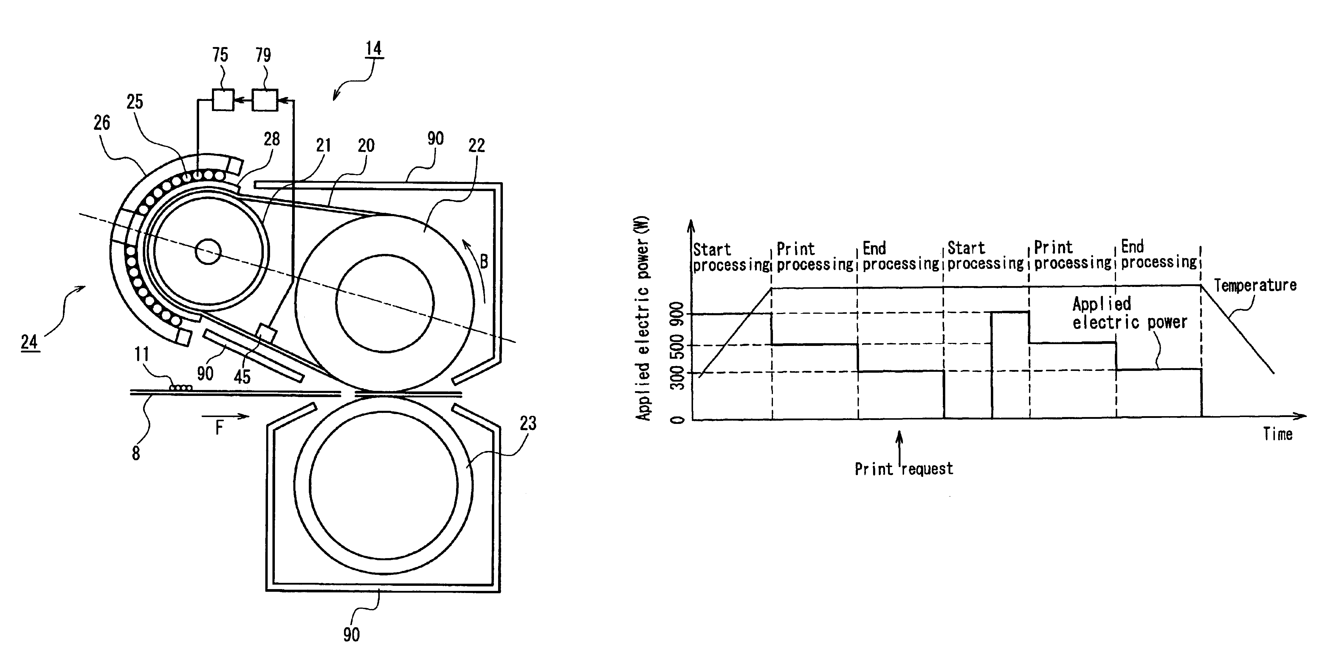
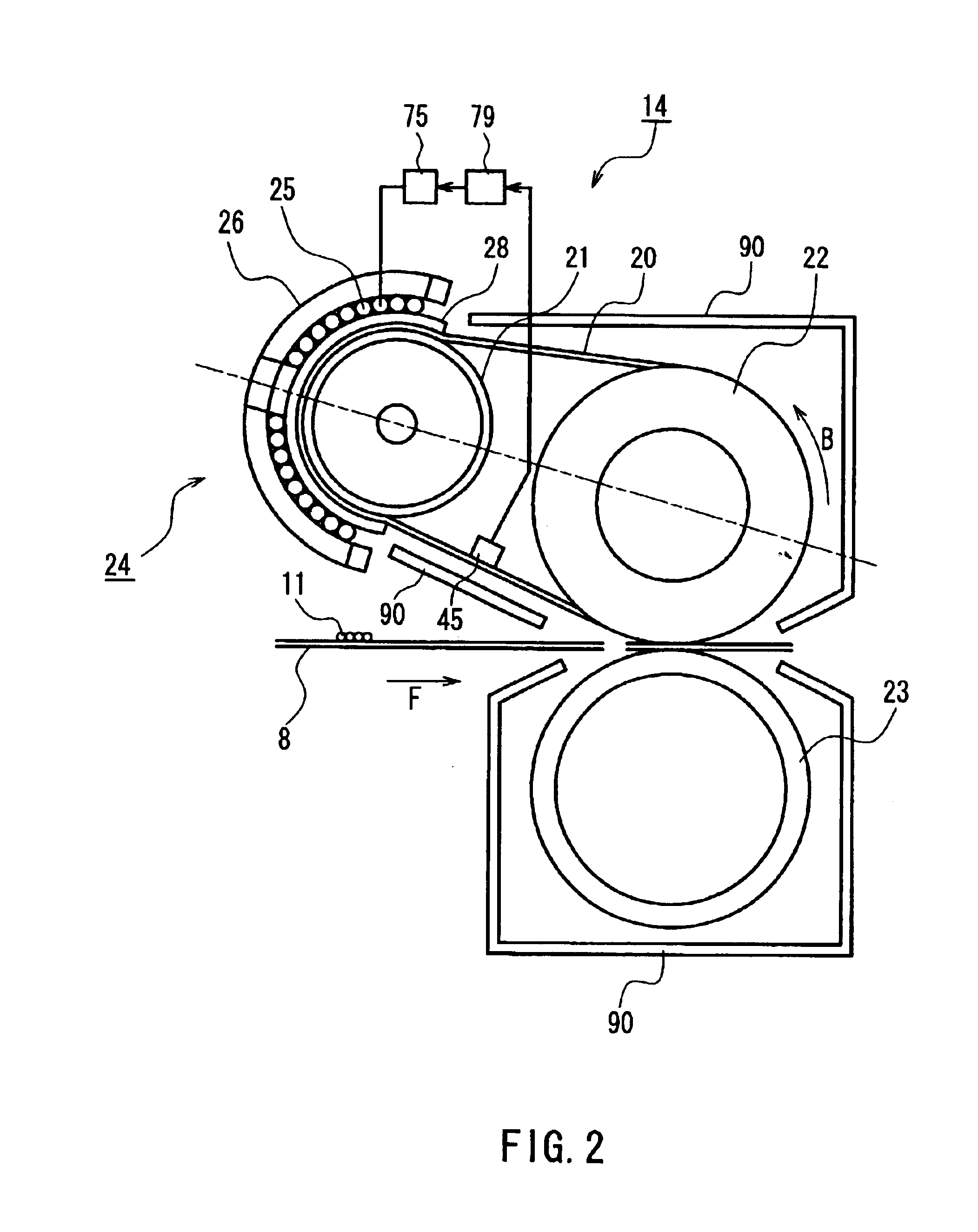
[0107]An image heating device of the second embodiment has the same configuration as that of the image heating device of the first embodiment as shown in FIG. 2. However, the second embodiment is different from the first embodiment in that, while temperature control in the first embodiment is performed to eliminate the irregularity in gloss caused in the recording sheet in the feed direction, temperature control in the second embodiment is performed to eliminate the irregularity in gloss caused in the recording sheet in the axial direction of the pressure roller 23.

[0108]Hereinafter, a method for controlling a temperature in a semicontinuous print mode will be described with reference to FIG. 5.

[0109]FIG. 5 is a flowchart illustrating a flow of a process for a fixing temperature control routine applied to an image heating device and an image forming apparatus according to the present embodiment.

[0110]In FIG. 5, first of all, when a print request is issued by the u...

third embodiment

(Third Embodiment)

[0114]FIG. 6 is a cross-sectional view showing an overall configuration of a color image forming apparatus according to a third embodiment of the present invention, which uses as a fixing device an image heating device according to the first or second embodiment.

[0115]In FIG. 6, the right-hand face is the front face of the color image forming apparatus, on which a front door 67 is provided. Numeral 68 denotes a transfer belt unit including an intermediate transfer belt 69, three support axes 70 suspending the intermediate transfer belt 69, and a cleaner 71, which are formed in one piece and attached to the color image forming apparatus in a freely attachable and detachable manner. In this case, as shown in FIG. 6, the transfer belt unit 68 can be attached / detached to / from the color image forming apparatus after opening the front door 67.

[0116]On the left side of the interior of the color image forming apparatus, a carriage 73 is provided adjacent to the transfer be...


PUM


Abstract

A fixing device as an image heating device is provided, by which a difference in glossiness is not caused in a recording medium in the axial direction of a pressure roller. When a print request is issued during the end-processing sequence, an electric power applied to a magnetization coil via an exciting circuit is dropped to 0 by controlling means during the start-processing sequence, and after an appropriate interval, the heating with full power is restarted by the controlling means. By so doing, the decrease in temperature at both ends of a fixing belt and a heat-generating roller in the axial direction can be compensated.

Description

BACKGROUND OF THE INVENTION[0001]1. Field of the Invention[0002]The present invention relates to an image heating device that is suitable as a fixing device for fixing an unfixed toner image by heating a conductive belt directly or indirectly via a metal roller utilizing electromagnetic induction; an image forming apparatus, such as an electrophotographical apparatus or an electrostatic recording apparatus, using such an image heating device; an image copying machine using such an image forming apparatus; and a method for controlling temperature applicable to such an image heating device, an image forming apparatus, and an image copying machine.[0003]2. Description of the Related Art[0004]As image heating devices typically used for fixing devices, contact-heating type image heating devices such as roller-heating type devices and belt-heating type devices generally have been used.[0005]In recent years, due to the demand for shorter warm-up time and reduced energy consumption, electro...

Claims


Application Information

Patent Timeline
Patent Type & Authority Patents(United States)
IPC IPC(8): G03G15/20
CPCG03G15/2042G03G15/205G03G2215/2016G03G2215/2032G03G2215/2035G03G2215/00805
Inventor TATEMATSU, HIDEKIASAKURA, KENJIIMAI, MASARUSHIMIZU, TADAFUMISAMEI, MASAHIROMATSUZAKI, KEIICHIMATSUO, KAZUNORIKITAGAWA, SHOICHI
Owner PANASONIC CORP
Why Eureka
Eureka Blog
Learn More