
System for transmitting digital signals with FM signals

a digital signal and fm signal technology, applied in the field of radio broadcasting, can solve the problems of affecting the performance of other signals, distortion of combined signals, and difficulty in keeping signals isolated from each other, and achieve the effect of reducing power loss and maintaining isolation of signals

Inactive Publication Date: 2005-08-23
SPX CORP
View PDF2 Cites 6 Cited by
  • Summary
  • Abstract
  • Description
  • Claims
  • Application Information

AI Technical Summary

Benefits of technology

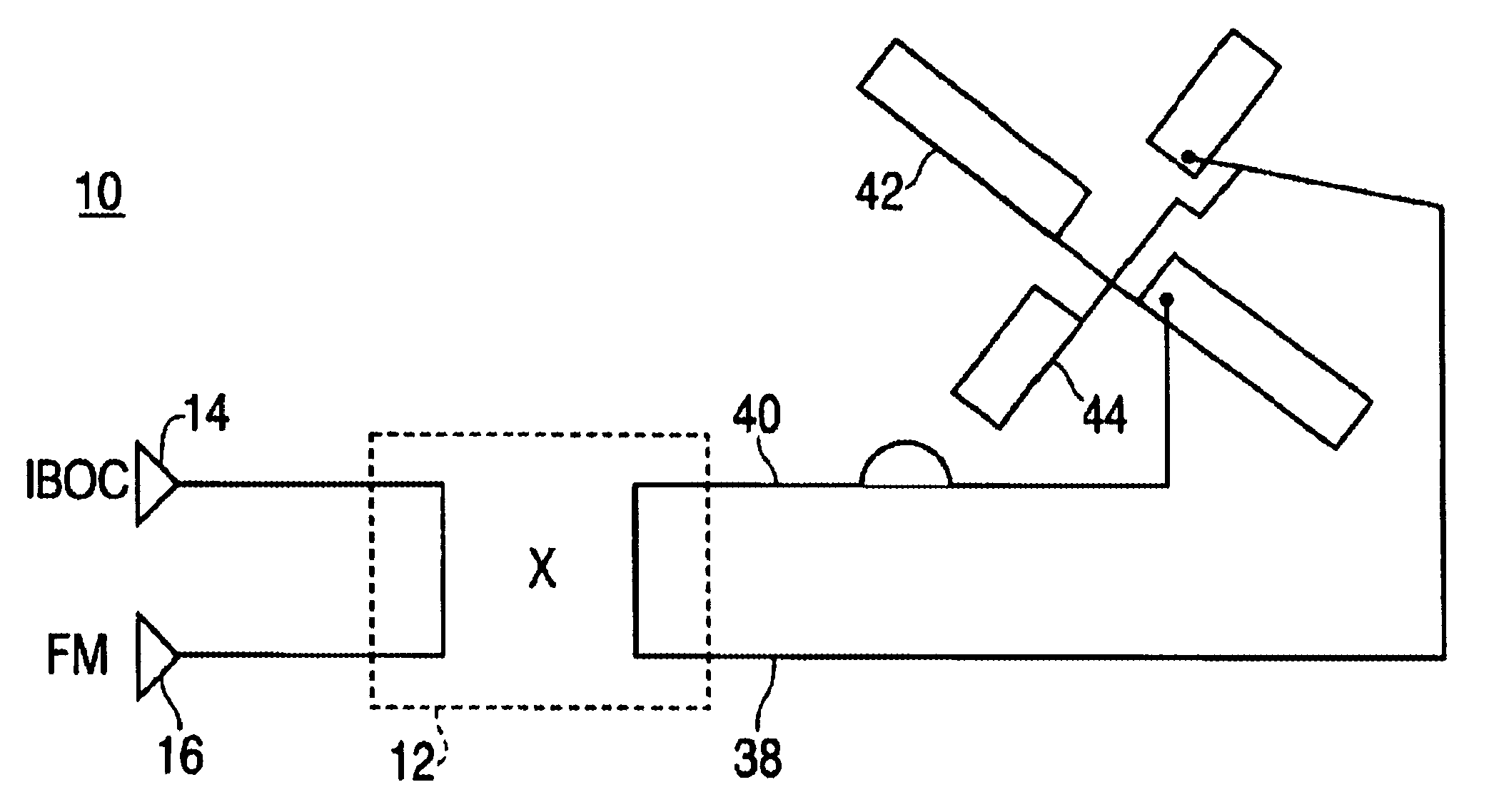
[0016]According to the system for transmitting FM signals with digital signals of the present invention, it is possible to eliminate power lost by the FM signals and the digital signals, when they are combined. The use of the coupler and the cross-polarized two dipole members make it possible to maintain isolation of the signals. The hybrid coupler maintains isolation of the FM signals and the digital signals before they are fed into the transmitting antenna, while the cross-polarized dipole members maintain isolation of the FM signals and digital signals at the transmitting antenna. As a result, essentially all of both signals appear at the antenna.

Problems solved by technology

A disadvantage of the Hybrid IBOC DAB approach is the difficulty associated with keeping the signals isolated from each other, in such a way as to avoid intermodulation product generation in the transmitters.
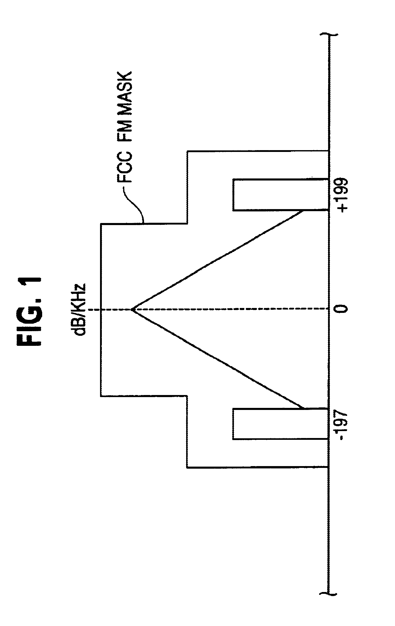
In-band intermodulation products generally cause distortion in the combined signal, and out-of-band intermodulation products generally affect the performance of other signals in adjacent channels.
However, utilizing filters in combining systems to provide isolation between the signals would be difficult because it would require a system having a large number of high quality factor (Q) sections.
This approach would be difficult and costly to implement.
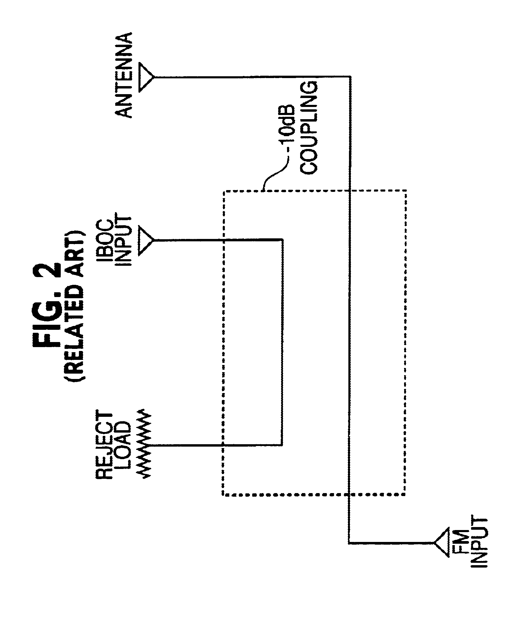
A disadvantage to this, however, is the loss of power suffered by the FM signal.
The insertion loss of the FM signal is significant although the amount of power lost by the FM signal is low compared to the amount of power lost by the digital signal.
Although a system utilizing a single −10 dB quadrature hybrid coupler does provide for the isolation of the signals during transmission, it is inefficient because of the power lost in the reject loads.

Method used


Image

  • System for transmitting digital signals with FM signals
  • System for transmitting digital signals with FM signals
  • System for transmitting digital signals with FM signals

Examples


Embodiment Construction

[0023]Referring now to FIG. 3, there is shown a preferred embodiment of a system 10 for transmitting digital signals with FM signals, according to the present invention. As shown in FIG. 3, the system includes a coupler 12 that receives, at separate inputs, a digital signal 14 and an FM signal 16. In an exemplary embodiment, the coupler may be a +3 dB quadrature hybrid coupler or any other suitable device.

[0024]The coupler 32 acts as a splitter. It splits the FM signal into two parts of equal amplitude, but with a phase difference of 90 degrees. The coupler 32 outputs one part of the FM signal to feed line 38, for example the part at 0 degrees, and outputs the other part of the FM signal, the part at 90 degrees, to feedline 40. Similarly, coupler 32 splits the digital signal into two parts. However, it feeds the 0 degree part of the digital signal to feedline 40, which transmits the 90 degrees part of the FM signal, and transmits the 90 degree part to feedline 38, which transmits th...


PUM


Abstract

A system for transmitting digital signals in the same band and on the same channel with FM signals is disclosed. The design of the system according to the present invention includes a coupler, which may be a +3 dB hybrid quadrature coupler, and circularly polarized antenna. The +3 dB hybrid quadrature coupler maintains isolation between the FM signals and the digital signals. The circularly polarized antenna receives the FM signals and the digital signals, and transmits the signals after they have each been separately received at the circularly polarized antenna.

Description

FIELD OF THE INVENTION[0001]The present invention relates generally to radio broadcasting. More particularly, the present invention relates to providing a system for transmitting digital signals in the same band and on the same channel with frequency-modulated (FM) signals.BACKGROUND OF THE INVENTION[0002]Broadcast frequency spectrum is a resource in which the demand, compared to the spectrum availability, is high because there are many other forms of broadcast communication, such as television, radio, and wireless communication services, that also require bandwidth for transmitting data. The use of the spectrum is therefore highly regulated by the Federal Communications Commission (“FCC”).[0003]Digital communication is becoming a more common method for broadcast communication. In general, digital communication allows for the delivery of communication services that are of a better quality than counterpart analog methods of communication and can be made to be faster and more efficien...

Claims


Application Information

Patent Timeline
Patent Type & Authority Patents(United States)
IPC IPC(8): H04H1/00H04B1/40H04H20/30
CPCH04H20/30H04B1/406
Inventor STENBERG, JAMES T.
Owner SPX CORP
Learn More