Method and apparatus for precise positioning of large structures

Inactive Publication Date: 2005-08-23
TRIMBLE NAVIGATION LTD
View PDF29 Cites 40 Cited by
  • Summary
  • Abstract
  • Description
  • Claims
  • Application Information

AI Technical Summary

Benefits of technology

[0010]According to one embodiment, a three dimensional structure is precisely positioned at a desired location. To begin, a virtual model of the structure of interest is created and stored in a computer memory. Some time later, remote sensors are placed in selected positions on the actual structure of interest. The sensors are configured so as to provide real time location, attitude and orientation information regarding the structure and may consist of GPS remote units, tilt meters, gyro compasses, and pressure sensors. The position of each remote sensor on the actual structure is also recorded in the computer memory so that the virtual model of the structure accurately reflects the real world situation. As the structure is being positioned, real time location, attitude and orientation information produc

Problems solved by technology

Displacements which are accidentally built into the path of a bridge, for example, may require expensive correction before the bridge can be placed in operatio

Method used


Image

  • Method and apparatus for precise positioning of large structures
  • Method and apparatus for precise positioning of large structures
  • Method and apparatus for precise positioning of large structures

Examples


Embodiment Construction

[0019]Referring to the drawings in detail wherein like numerals designate like parts and components, the following description sets forth numerous specific details in order to provide a though understanding of the present invention. However, after reviewing this specification, it will be apparent to those skilled in the art that the present invention may be practiced without some or all of these specific details. In other instances, well known structures, programming techniques and devices have not been described in detail in order not to unnecessarily obscure the present invention.

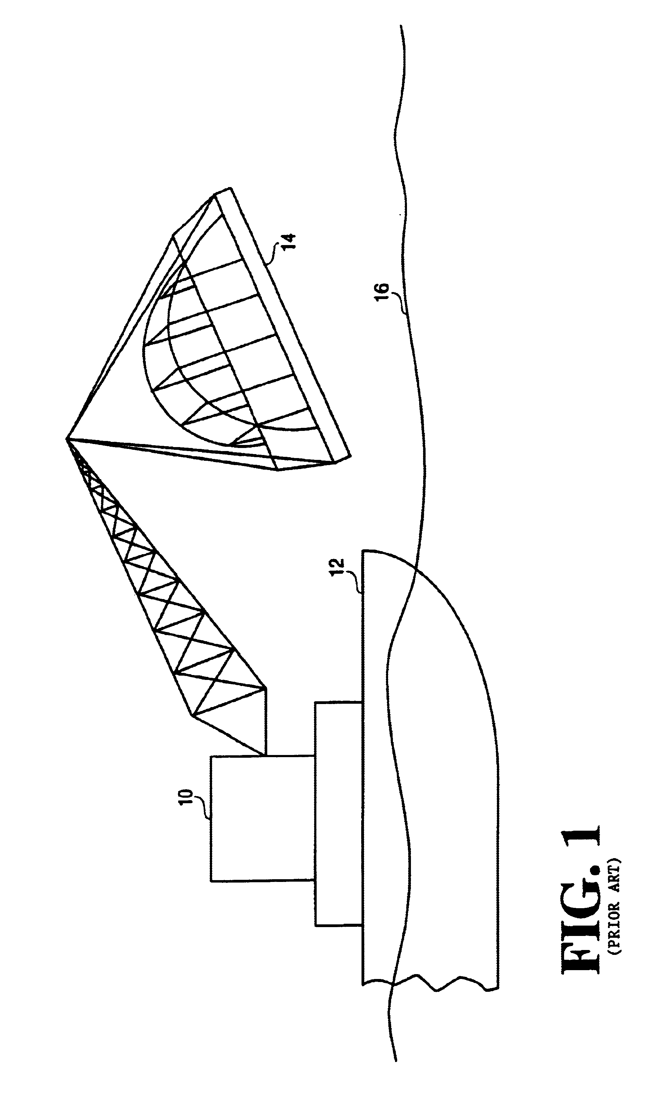
[0020]FIG. 1 illustrates the precise positioning of a bridge section or other large structure according to the present invention. Crane 10 is situated on barge 12 and is in the processes of positioning bridge section 14. Barge 12 may be in the process of navigating a waterway 16 such as a channel or port. As will be described below, the positioning of bridge section 14 is aided by the use of a variety of ...


PUM


Abstract

A three dimensional structure is precisely positioned at a desired location. A viral model of the structure of interest is created and stored in a computer memory. Some time later, remote sensors are placed in selected positions on the structure of interest. The sensors are configured so as to provide real time location, attitude and orientation information regarding the structure and may consist of GPS remote units, tilt meters, gyro compasses, and pressure sensor. The position of each the remote sensors on the actual structure is also recorded in the computer memory so that the virtual model accurately reflects the configuration of the structure. As the structure is being positioned, the real-time location, attitude and orientation information produced by the remote sensors is monitored at a base station and used to update the virtual model. In this way, the virtual model accurately reflects the current location, attitude and orientation of the structure. The information so obtained can be displayed to a user as a graphical and textual representation of the current state of the structure. The desired location, attitude and orientation of the structure is also displayed, thereby allowing a user to adjust the current location, attitude and orientation of the structure so as to align the current position of the structure to desired position. As built reports are produced upon completion of the positioning operation.

Description

[0001]This application is a Divisional of application Ser. No. 08 / 676,719, filed Jul. 8, 1996, now U.S. Pat. No. 5,883,817.FIELD OF THE INVENTION[0002]The present invention relates generally to real time navigation systems and, more particularly, to the use of such systems for the precise positioning of large structures.BACKGROUND[0003]In the marine environment, construction personal are often faced with task of positioning large, three dimensional structures within confined spaces. For example, during construction in ports and other areas, it is common for structures such as bridge sections and tunnel sections to be moved by crane and barge into a desired location. Also, during the construction of oil-rig platforms, it is common for large pilings to be placed on the ocean floor using a piling-rig.[0004]Accurate, on going determination of the position of structures such bridge sections is required during all phases of the construction operation. In order that the bridge be properly ...

Claims


Application Information

Patent Timeline
IPC IPC(8): G01S5/02G01S5/14G01S19/14G01S19/53
CPCG01S19/13G01S19/53
Inventor CHISHOLM, GARY SEDMANHANSBY, MICHAELO'MEAGHER, BRENTMONNOX, ALAN
Owner TRIMBLE NAVIGATION LTD
Why Eureka
Try Eureka