Heat dissipation assembly

a technology of heat dissipation assembly and heat sink, which is applied in the direction of indirect heat exchanger, lighting and heating apparatus, and semiconductor/solid-state device details. it can solve the problems of unduly inconvenient and inability to apply heat grease to the heat sink in advan

Inactive Publication Date: 2005-08-30
HON HAI PRECISION IND CO LTD
View PDF12 Cites 30 Cited by
  • Summary
  • Abstract
  • Description
  • Claims
  • Application Information

AI Technical Summary

Benefits of technology

[0007]Accordingly, an object of the present invention is to provide a heat dissipation assembly having a heat sink and a grease cover readily attached to or detached from the heat sink.

Problems solved by technology

However, thermal grease cannot be applied to the heat sink in advance since it is not solid at ambient temperature and may contaminate surrounding articles or be contaminated by dust or foreign particles before the heat sink is attached to the CPU.
This is unduly inconvenient.

Method used


Image

  • Heat dissipation assembly
  • Heat dissipation assembly
  • Heat dissipation assembly

Examples


Embodiment Construction

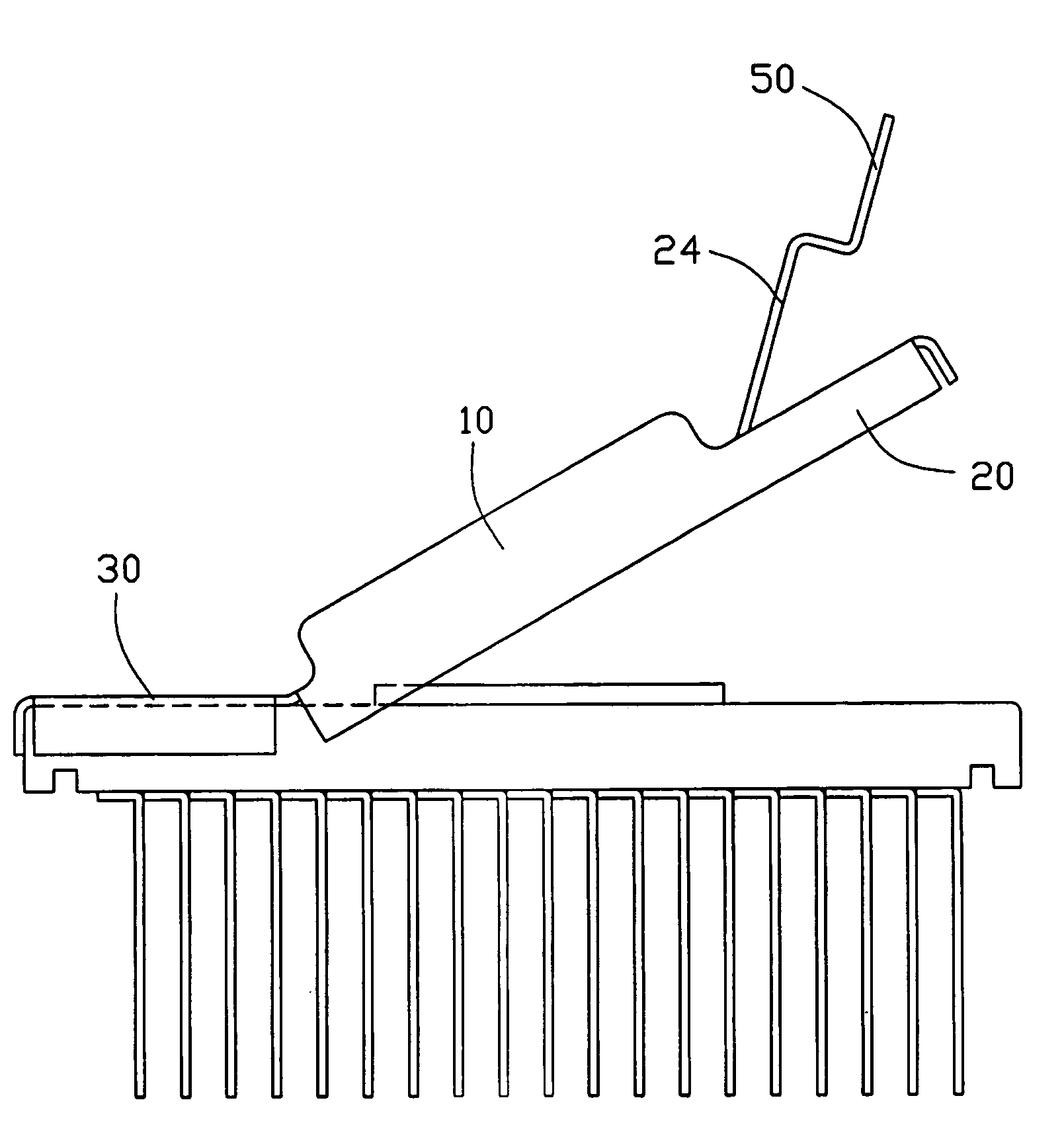
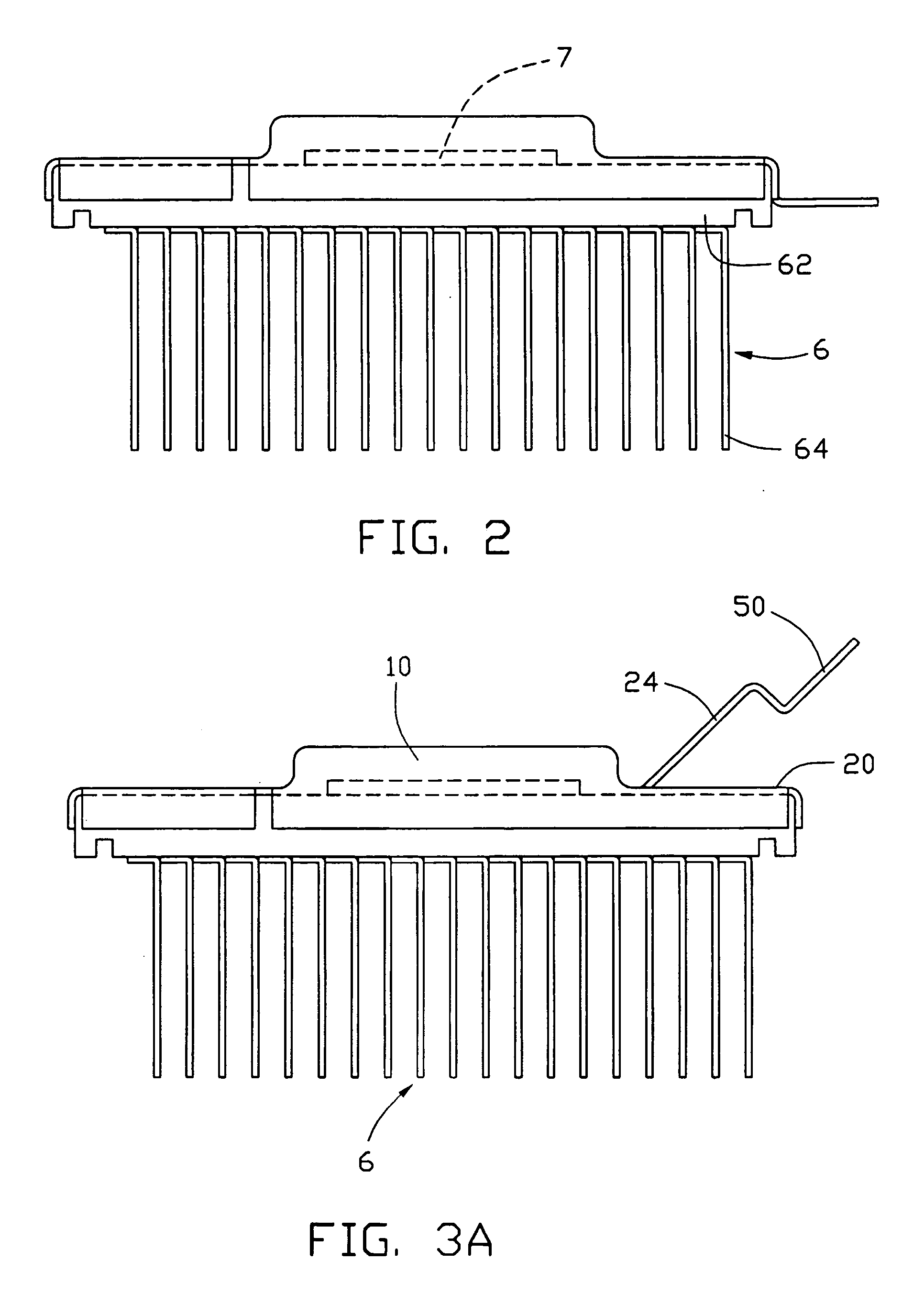
[0013]The heat dissipation assembly in accordance with the preferred embodiment of the present invention comprises a heat sink 6, thermal interface material 7 such as thermal grease which is applied to the heat sink 6, and a cap 1 employed to the heat sink 6 for preventing the thermal interface material 7 from being contaminated by dust or foreign particles before the heat sink 6 is attached to a CPU (not shown).

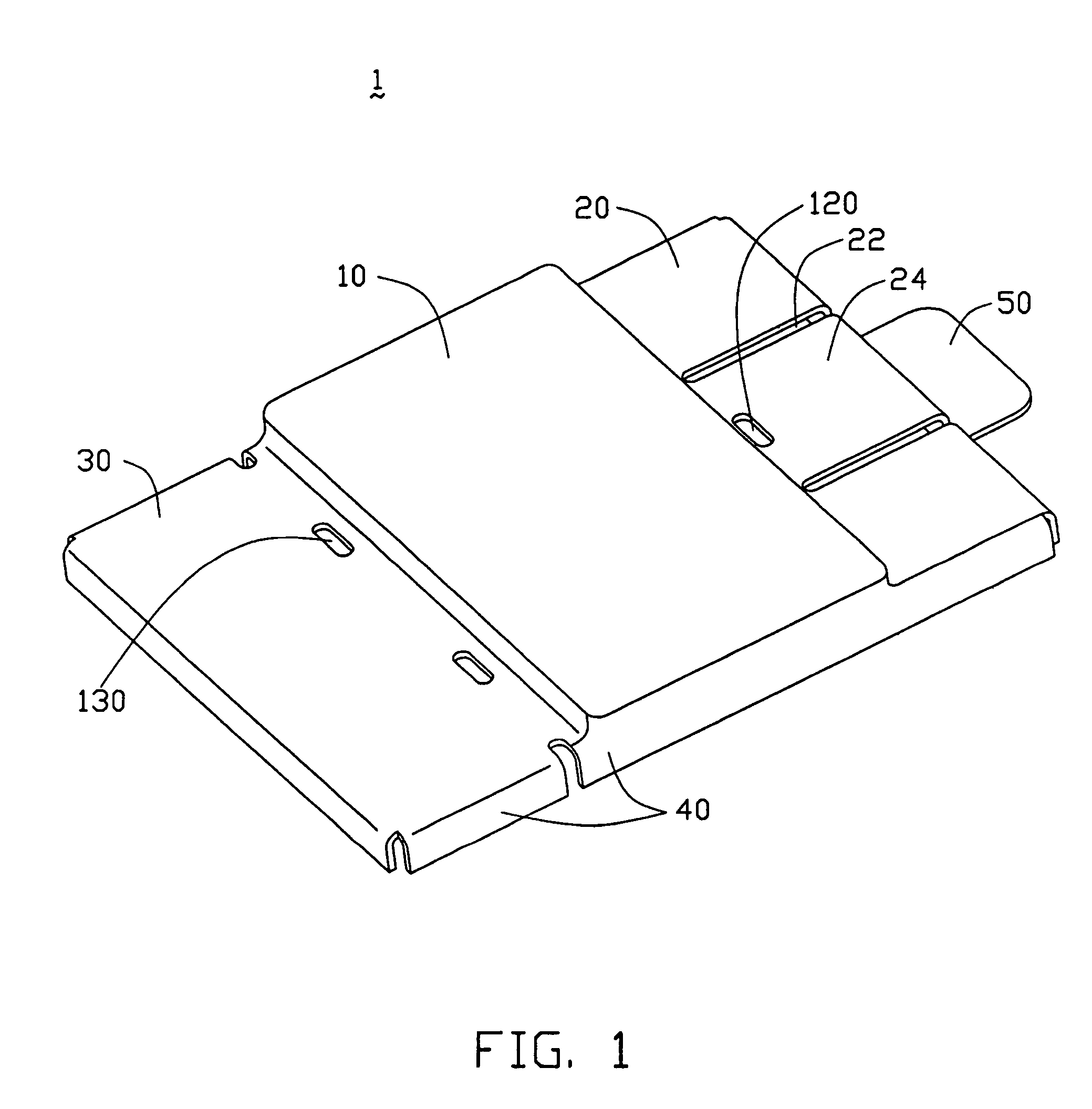
[0014]FIG. 1 shows the cap 1 which can be employed to the heat sink 6. The cap 1 integrally comprises a body 10, a first wing 20, a second wing 30, a flange 40 and a tab 50. The first and second wings 20, 30 extend from opposite edges of the body 10 respectively. The flange 40 extend perpendicularly from outer edges of the body 10, the first and second wings 20, 30. The tab 50 extends perpendicularly from an outer edge of the flange 40, for facilitating detachment of the cap 1 from the heat sink 6. A pair of parallel grooves 22 is defined in the first wing 20 and divides the...


PUM


Abstract

A heat dissipation assembly includes a heat sink having a base and a plurality of heat dissipation fins disposed on the base, thermal interface material applied to the base opposing the fins, and a cap covering the base. The cap includes a body which shields the thermal interface material, and first and second wings extending from the body. The first wing is rotatable relative to the body to facilitate detaching the cap from the base of the heat sink.

Description

BACKGROUND OF THE INVENTION[0001]1. Field of the Invention[0002]The present invention relates to a heat dissipation assembly having a heat sink, and more particularly to a heat dissipation assembly having a removable protective cap for enclosing thermal grease on the heat sink, thereby protecting the thermal grease from contamination before the heat sink is assembled to a CPU / CPU module.[0003]2. Description of Prior Art[0004]As computer technology continues to advance, electronic components such as central processing units (CPUs) of computers are being made to provide faster operational speeds and greater functional capabilities. When a CPU operates at high speed in a computer enclosure, its temperature can increase greatly. It is desirable to dissipate the generated heat quickly, for example by using a heat sink attached to the CPU in the enclosure. This allows the CPU and other electronic components in the enclosure to function within their normal operating temperature ranges, the...

Claims


Application Information

Patent Timeline
Patent Type & Authority Patents(United States)
IPC IPC(8): F28F7/00H01L23/34H01L23/42
CPCH01L23/42H01L2924/0002H01L2924/00
Inventor DONG, SHUN CHIHUANG, CHUNG-YUAN
Owner HON HAI PRECISION IND CO LTD
Why Eureka
Try Eureka