
Wire retainer

a technology of wire retainer and wire, which is applied in the field of wire retainer, can solve the problems of difficulty in inserting wire into the retainer, inconvenient handling, and problems in respect of working efficiency, and achieve the effects of convenient insertion, convenient fixing, and convenient insertion

Inactive Publication Date: 2005-08-30
ORION ELECTRIC CO LTD
View PDF10 Cites 57 Cited by
  • Summary
  • Abstract
  • Description
  • Claims
  • Application Information

AI Technical Summary

Benefits of technology

"The invention is a wire retainer that makes it easy to mount wires on a circuit board. The retainer is made of a flexible material and has a base part and a restriction part. The retainer can be fixed to the circuit board using a protrusion. The retainer has an inserting port for wires, and the wire is securely inserted into the retainer. The retainer is also easy to automate and can be used to replace non-use holes in the circuit board. The base part increases the number of wires that can be retained, and the upper portion of the retainer is covered with insulating material to prevent short of electricity. The protrusion ensures secure fixation of the retainer to the circuit board. Overall, the wire retainer simplifies the process of mounting wires on a circuit board."

Problems solved by technology

If the wires such as a cable and so forth are disposed on the circuit board as they are, they are inconvenient to handle and there is a likelihood that they are caught carelessly to come off from the circuit board, and hence a wire retainer for holding a cable on the circuit board is used.
However, in the case where the flexible material is used for a retainer, the wire is prone to come off as disclosed in the first reference, and hence it is considered to select a material having less flexibility, which is however make it difficult to insert the wire into the retainer.
Further, although it is surely possible to prevent the wire from being come off from the retainer if the retainer is deformed to wind around the wire, it needs a winding operation, causing a problem in respect of working efficiency.
Further, according to the conventional wire retainer, since it is necessary to provide holes for the wire retainer on the circuit, the necessity of such holes has to be considered in advance at the stage of designing the circuit board, resulting in restrictions on the design of the circuit board.
Still further, it is difficult to add the wire retainer when the wiring is necessitated at the stage where the electronic components were mounted on the circuit board.

Method used


Image

  • Wire retainer
  • Wire retainer
  • Wire retainer

Examples


first embodiment (figs.1 to 3)

[0019]First Embodiment (FIGS. 1 to 3)

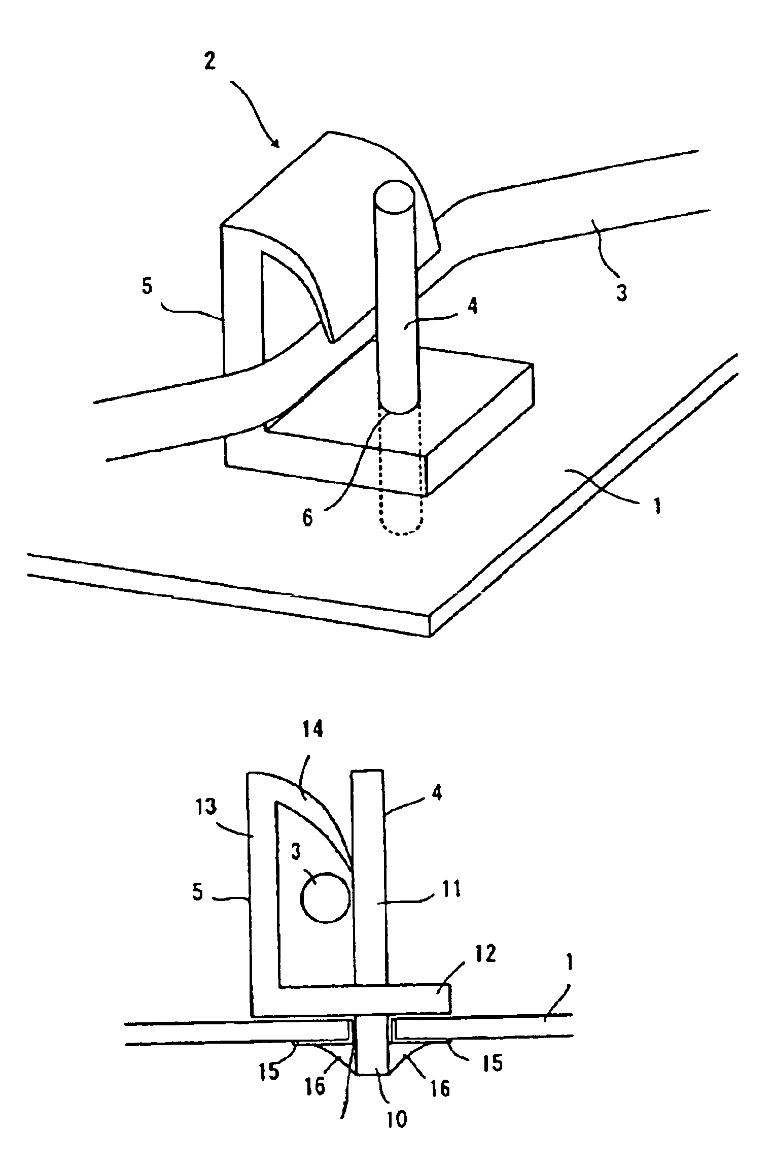
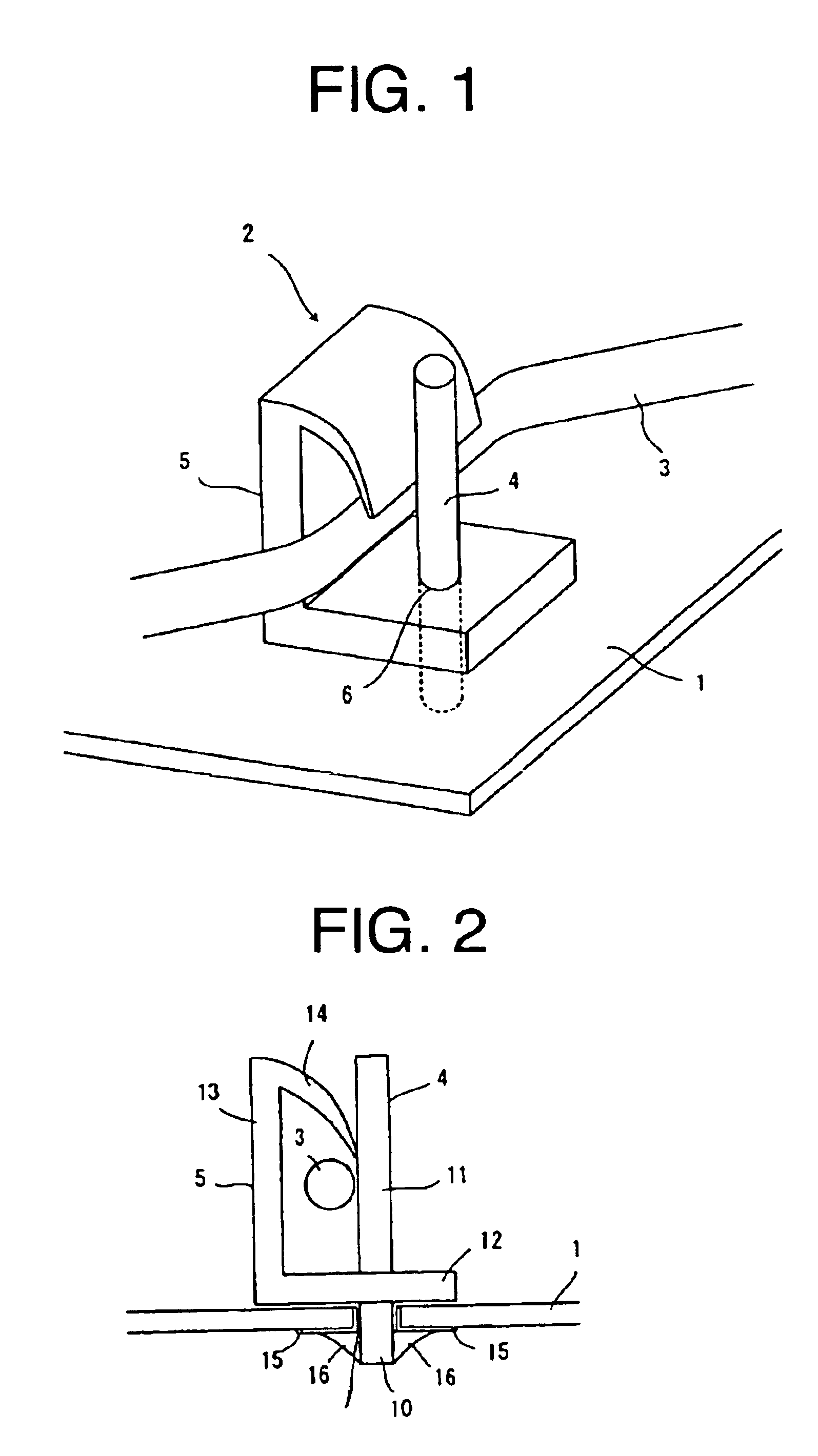
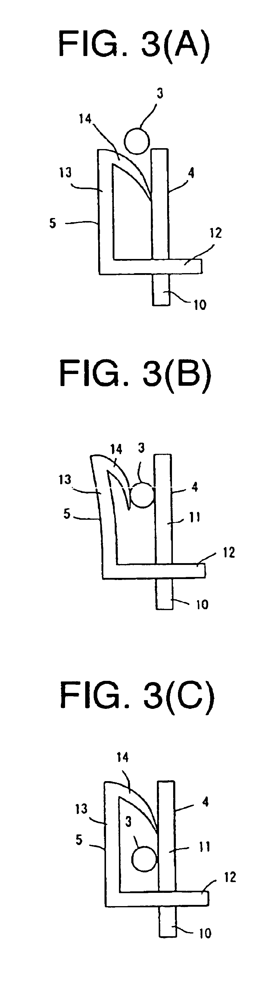
[0020]FIG. 1 is a schematic perspective view showing a state where a wire retainer is fixed onto a circuit board according to a first embodiment of the invention, and FIG. 2 is a schematic sectional view showing a state where the wire retainer is fixed onto the circuit board. A wire retainer 2 fixed onto a circuit board 1 is made up of a long cylindrical body 4 made of metal and serving as a supporting member and a retainer member 5 molded by a flexible material an the wire retainer 2 retains a wire 3 such as a lead wire.

[0021]The long cylindrical body 4 has a lower portion 10 fixed to the circuit board 1 (hereinafter referred to as fixed part 10), and the fixed part 10 is inserted into a hole 7 which is defined in the circuit board 1, and through which an electronic component is mounted on the circuit board 1, so that the fixed part 10 is fixed to the circuit board 1.

[0022]A conductive pattern 15 is printed in advance at the periphery of the hol...

second embodiment (fig.4)

[0026]Second Embodiment (FIG. 4):

[0027]FIG. 4 is a view of a wire retainer according to a second embodiment of the invention. According to the second embodiment, respective extension parts 13 project from opposite sides of a base part 12 of a retainer member 5 and restriction parts 14 are integrally molded with the extension part 13 at the upper ends thereof. Accordingly, it is possible to retain wires such as lead wires at both sides of the long cylindrical body 4 so that more wires can be retained.

third embodiment (fig.5)

[0028]Third Embodiment (FIG. 5):

[0029]According to a wire retainer of a third embodiment shown in FIG. 5, a protrusion 17 is formed on the lower surface of a base part 12 of a retainer member 5 and it is inserted into and mounted on a hole which is defined in a circuit board 1 when a wire retainer 2 is fixed to the circuit board 1. A fixed part 10 of a long cylindrical body 4 at the lower portion thereof has a bent part 18 by forming. In the third embodiment, since the fixed part 10 and the protrusion 17 are inserted into and fixed to two holes of the circuit board 1, the turning of the wire retainer 2 is prevented, so that the wire retainer 2 can be more firmly fixed to the circuit board 1. Since the bent part 18 is formed on the fixed part 10, the wire retainer 2 can be fixed to the circuit board 1 without effecting soldering, and hence it is suitable for a case where the wire retainer 2 is fixed to the circuit board 1, e.g., after the electronic components are mounted on the circ...


PUM


Abstract

It is an object of the invention to provide a wire retainer capable of easily mounting a wire on a retainer part and of simply fixing the wire retainer to a circuit board. A lower part of a long cylindrical body forms a fixed part which is fixed to the hole defined in the circuit board by a solder, and a base part of a retainer member is fixed to a substantially central part of the long cylindrical body. The base part has an extension part extending upward therefrom and a restriction part is fixed to an upper end of the extension part and extends downward along an upper portion of the long cylindrical body. A lead wire is inserted between the restriction part and the upper portion and retained by the retainer member.

Description

FIELD OF THE INVENTION[0001]The invention relates to a wire retainer to be used for retaining a wire such as a cable and so forth which is wired in the case of mounting electronic components on a circuit board.BACKGROUND OF THE INVENTION[0002]A circuit board on which semiconductor devices such as ICs, transistors, and electronic components such as resistors, capacitors are mounted has been used, and wires such as a cable and so forth for wiring the electronic components mounted on the circuit board. If the wires such as a cable and so forth are disposed on the circuit board as they are, they are inconvenient to handle and there is a likelihood that they are caught carelessly to come off from the circuit board, and hence a wire retainer for holding a cable on the circuit board is used.[0003]For example, JP 1993-226855A discloses that an engagement claw of a retainer is inserted into an engagement hole to fix the retainer, a protrusion is provided on a bow-shaped spring which is provi...

Claims


Application Information

Patent Timeline
Patent Type & Authority Patents(United States)
IPC IPC(8): H05K3/30H05K7/00H02G3/30
CPCH02G3/26H05K3/301
Inventor SONO, YOSHIYUKINOGOME, TOSHIYUKI
Owner ORION ELECTRIC CO LTD
Learn More