Snap fitting electrical connector

a technology of electrical connectors and clamp fittings, applied in the direction of connection contact member materials, coupling device connections, contact member manufacturing, etc., can solve the problems of many of the commonly known connectors being limited for use, improper or not properly grounded connectors used in such instances, and still exist slight variations and deviations within the accepted limit of established standards. , to achieve the effect of simple construction, economical fabrication and positive operation

Inactive Publication Date: 2005-08-30
BRIDGEPORT FITTINGS LLC
View PDF36 Cites 14 Cited by
  • Summary
  • Abstract
  • Description
  • Claims
  • Application Information

AI Technical Summary

Benefits of technology

[0010]An object of this invention is to provide an electrical connector having a novel retaining means for effecting a snap fit connection with an associated electrical box that requires a minimum of force and a maximum of ease.
[0011]Another object is to provide an electrical connector having an improved retaining ring that will insure a more positive grounding effect despite slight variations that may occur either in the construction of the electric box and / or the connector body.
[0013]Another object is to provide an electrical connector that is relatively simple in construction, positive in operation and economical to fabricate.
[0014]An object of this invention is to provide for a simpler and more expedient way of securing a threaded connector to an electric box.
[0016]Another object is to provide a snap fit retaining ring having staggered depressions or dimples for engaging the grooves of the threaded outlet end of the connector to prohibit any inadvertent separation of the connector from the electric box.

Problems solved by technology

However, even though such electrical boxes have been generally standardized, it has been noted that while such boxes may conform to the standards adopted, there still exists some slight variations and deviations that occur within the accepted limited of the established standard.
Such size variations can cause a connector used in such instance to be improperly or not properly grounded.
It has also been observed that many of the commonly known connectors are limited for use with only a specific type of electrical conductor, e.g. applicable for use only with helically wound armor or BX type cable or for use with non-metallic sheathed cables, or co-axial cables and the like.
While the connectors disclosed in said latter patents are provided with a spring steel adaptor to effect the securing of the connector to an electrical box, some difficulty and excessive force may be required to effect the connection, as the connector does not provide any relief space to accommodate the deflection of the spring tangs or fingers during insertion through the knock out opening of an electrical box.
It has been further observed that proper grounding may not be achieved in the event a given electrical box has a knock out opening which may be slightly oversized or the connector is slightly undersized, but still within the parameters of the adopted standards for electrical box and associated connectors.
In assembling such a connector to the electric box, one is required to use two hands, one for holding the connector in place while the other hand is used for threading the nut about the threaded outlet end of the connector, which is often rendered tedious, difficult and time consuming.
This is because the nut is required to be threaded onto the connector within the confines of the electric box where space and visibility is very restricted.

Method used


Image

  • Snap fitting electrical connector
  • Snap fitting electrical connector
  • Snap fitting electrical connector

Examples


Embodiment Construction

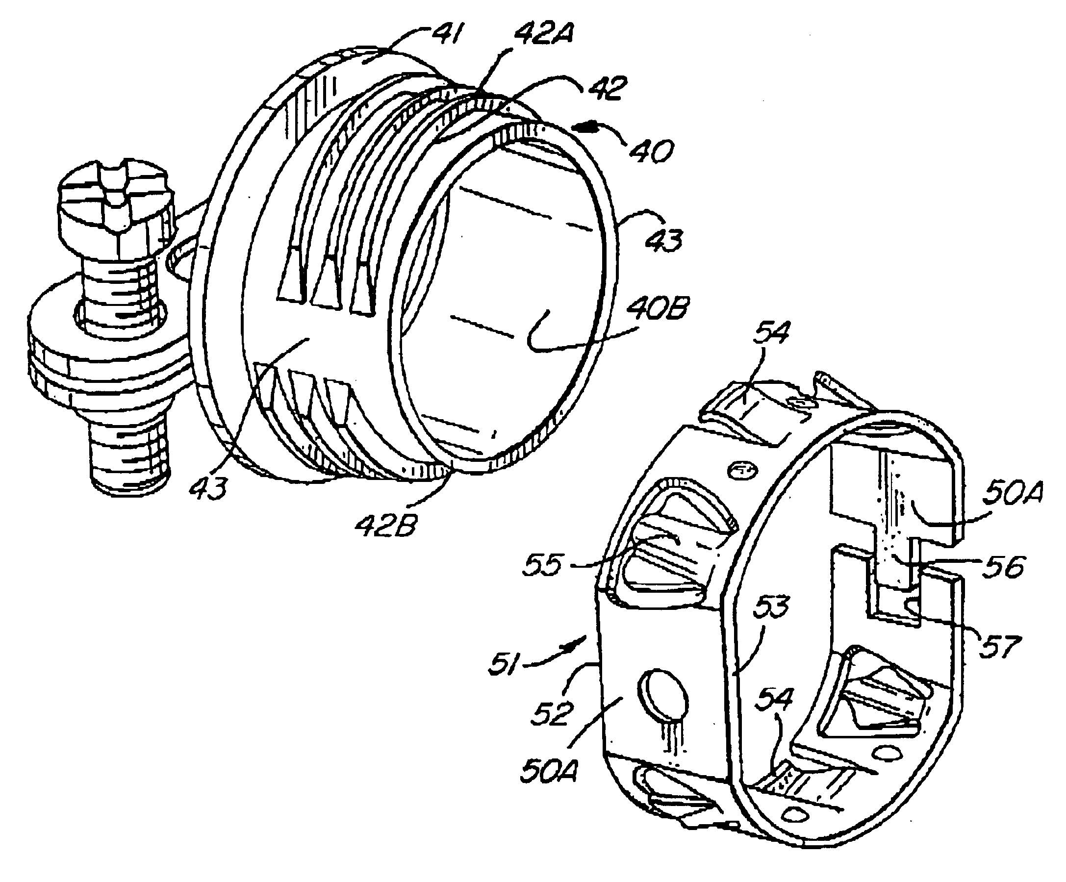
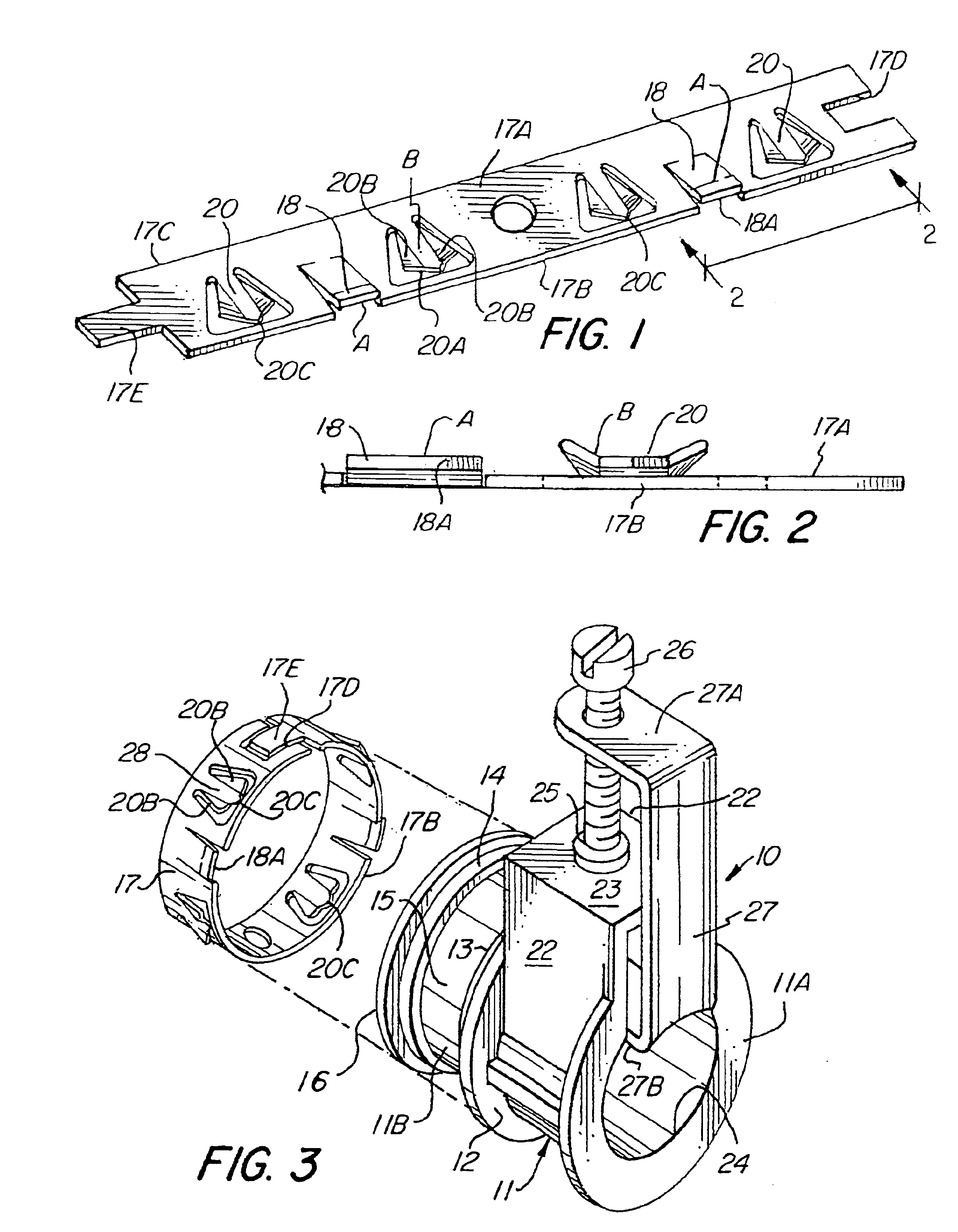
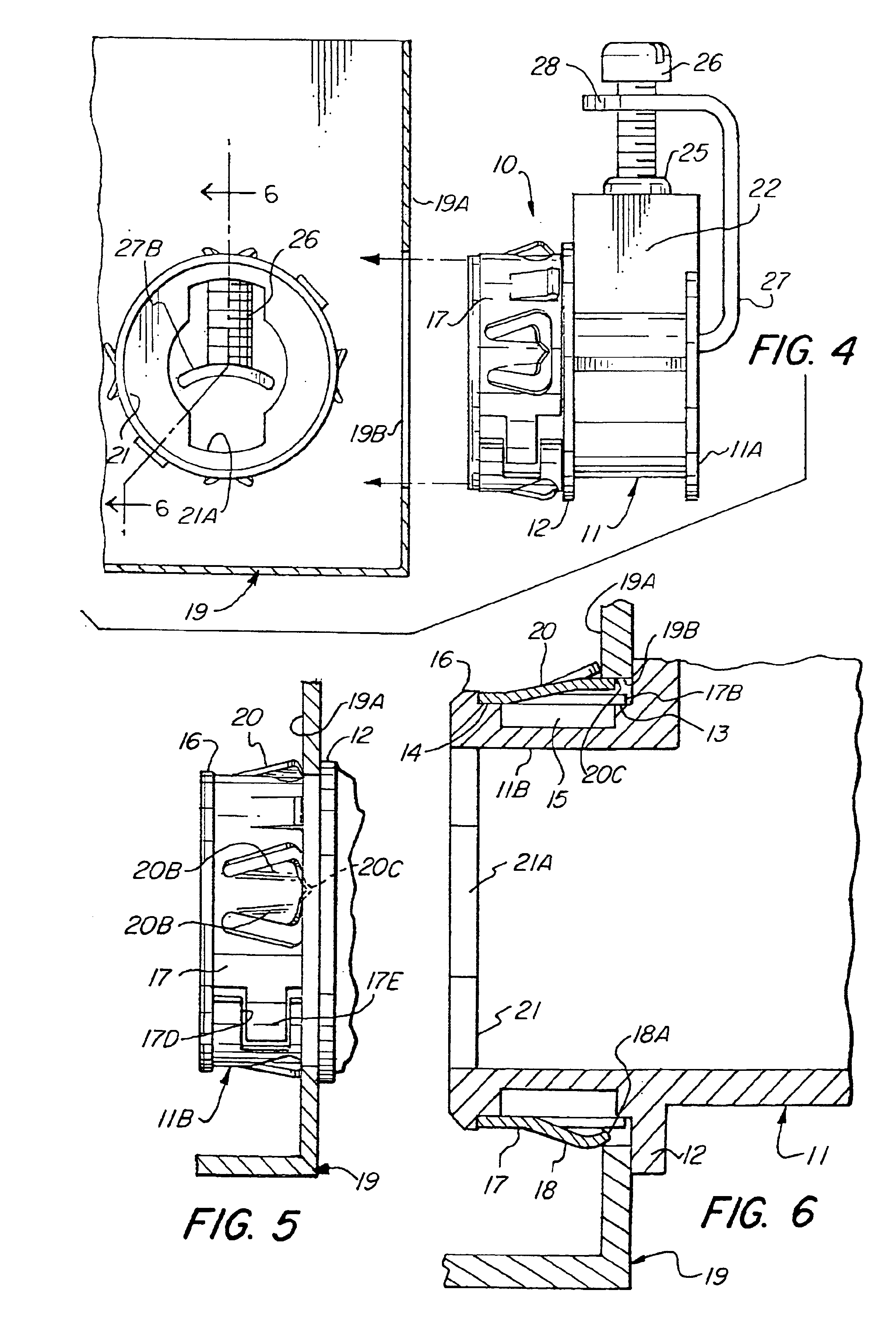
[0038]Referring to the drawings, there is illustrated an electrical connector 10 that embodies the instant invention. As shown, the electrical connector 10 includes a connector body 11 that has a cable or inlet end 11A and an outlet end 11B. The connector body 11 may be formed as a metal casting of any suitable metallic material such as zinc, aluminum, and / or any suitable metallic alloy. A radially outwardly extending intermediate flange 12 circumscribes the connector body 11 between the inlet end 11A and the outlet end 11B. The outlet end 11B is generally circular and is provided with a pair of spaced apart shoulders 13 and 14 circumscribing the outlet end 11B that define therebetween a space or recess 15. Circumscribing the outermost shoulder 14 is a radially outwardly extending end flange 16.

[0039]In accordance with this invention, a specially constructed retaining or snap fit ring 17 is loosely supported on shoulders 13 and 14, as best viewed in FIG. 6. The retainer or snap fit ...


PUM


Abstract

An electrical connector having an inlet end and an outlet end wherein the leading or outlet end is provided with a pair of spaced apart shoulders defining therebetween an annular recess and a snap fit retainer ring fitted onto the outlet end, the retainer ring having at least two series of spring tangs blanked out of the plane thereof, and which tangs are formed to effect a positive grounding connection with an associated electric box in the event any slight deviations are encountered within the parameters of the adopted standards, and whereby the annular recess functions to provide a relief for the spring tangs to facilitate and minimize the required insertion force and to insure a positive ground connection between the connector and the electrical box in the assembled position. In another form of the invention, the snap fit retaining ring is provided with longitudinally and / or laterally spaced depressions transversely the width of the snap fit retaining ring for use on a connector formed with a threaded end.

Description

RELATED APPLICATION[0001]This application is a continuation in part application of a application Ser. No. 10 / 283,978 filed Oct. 30, 2002 for Snap Fitting Electrical Connector, now U.S. Pat. No. 6,860,758 B1.FIELD OF THE INVENTION[0002]This invention relates to an electrical connector for connecting an electrical conductor to an electrical box, and more specifically to an electrical connector that can be readily connected to an electrical box with a snap fit.BACKGROUND OF THE INVENTION[0003]Connectors for attaching an electrical conductor to an electrical box or junction box and the like are well known in the art. Such electric boxes, junction boxes, fuse boxes and the like are uniformly used in virtually all residential and commercial buildings, and buildings in general. As a result, such electrical boxes have been standardized. However, even though such electrical boxes have been generally standardized, it has been noted that while such boxes may conform to the standards adopted, t...

Claims


Application Information

Patent Timeline
Patent Type & Authority Patents(United States)
IPC IPC(8): H01R13/74H01R4/36H01R4/28H01R4/64H01R43/16
CPCH01R4/363H01R4/646H01R13/745H01R43/16
Inventor KIELY, KENNETH M.
Owner BRIDGEPORT FITTINGS LLC
Why Eureka
Try Eureka