
Non-interruptible battery changing system

Inactive Publication Date: 2005-08-30
VERMONT MEDICAL
View PDF4 Cites 23 Cited by
  • Summary
  • Abstract
  • Description
  • Claims
  • Application Information

AI Technical Summary

Benefits of technology

[0006]This invention receives an encased battery pack into a battery chamber which can be exchanged or replaced with another identical battery pack without interrupting the current to the system connected to electrical circuit loads, e.g. a battery operated video monitor system in which the battery supplied power to the LCD monitor as well as a video camera and an illumination system. The combination of all three load components resulted in a current draw to be high 750 ma to 1000 ma depending of the functions being used. The system according to the present invention is compact and light in weight so that using the more standard techniques of capacitors or secondary batteries unnecessary.
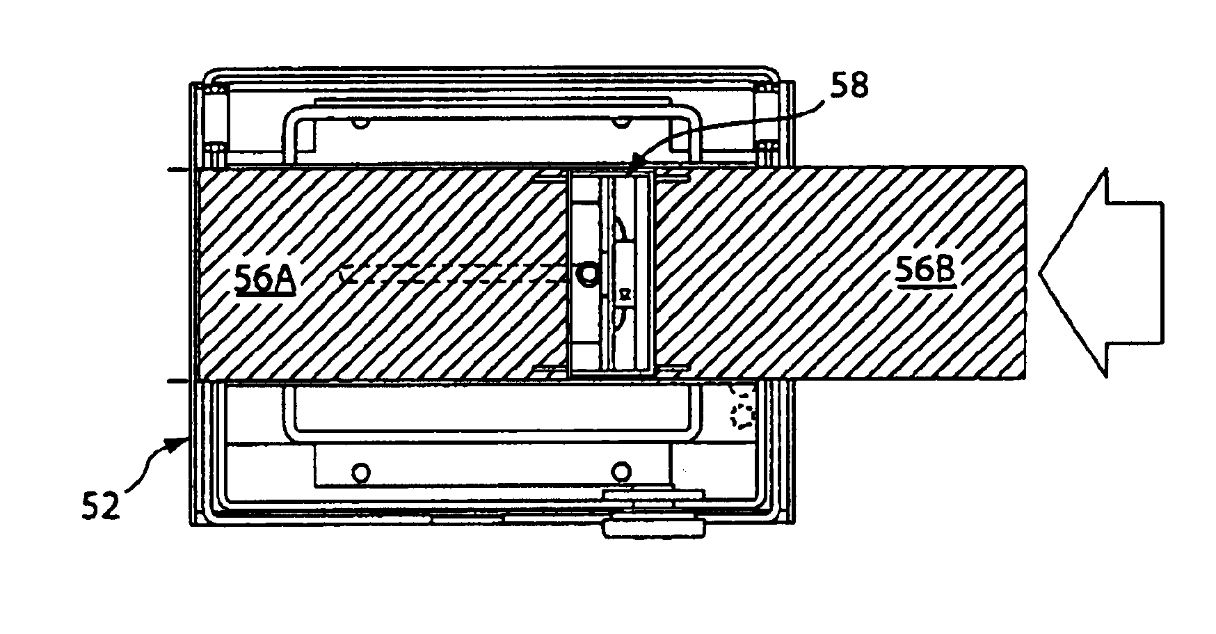
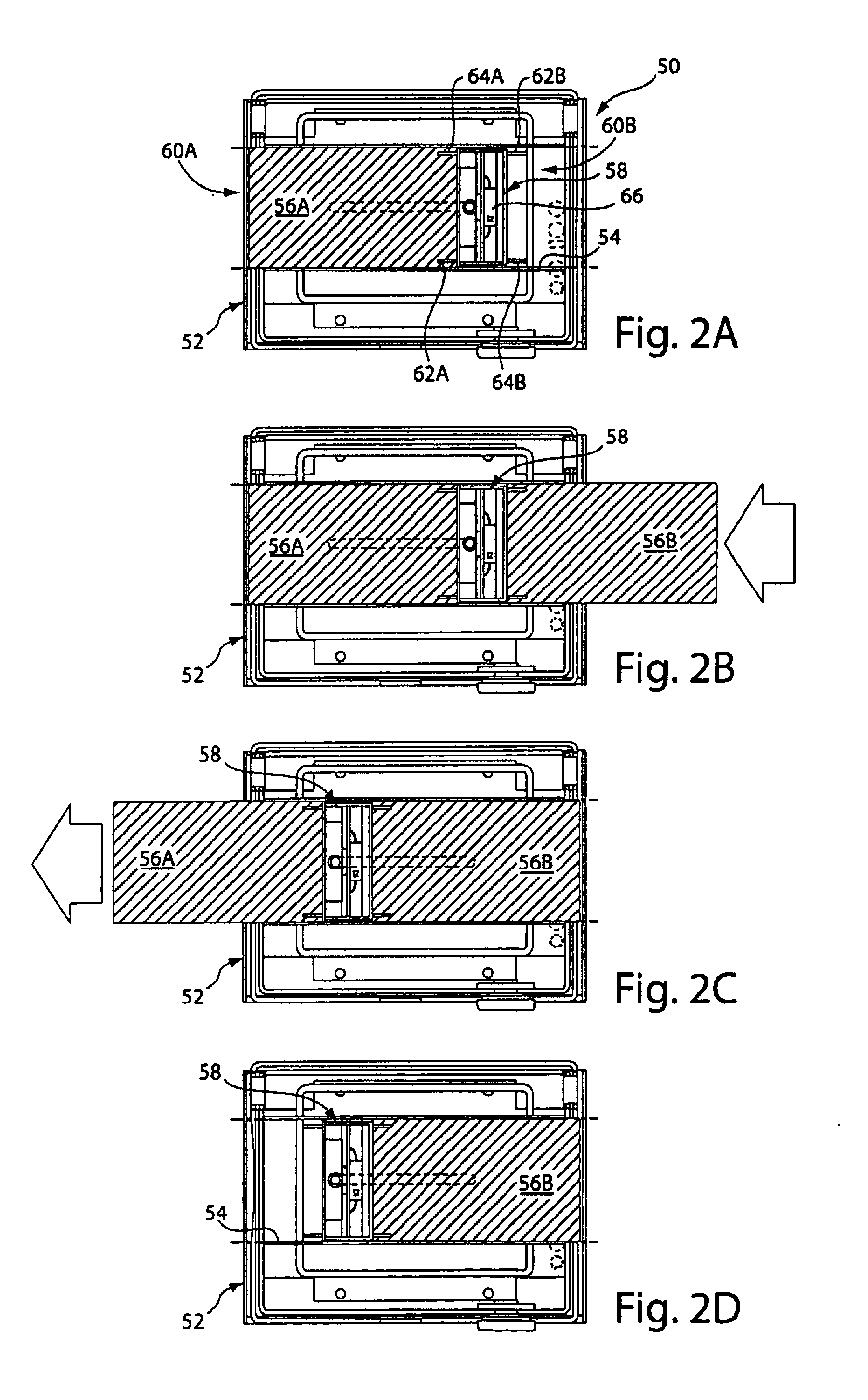
[0007]The preferred embodiment of the invention solved the above problems by allow sliding the battery pack in from both sides of the monitor case. Once the battery is fully inserted it is flush with the outside of the case. When the battery is low another battery is inserted from the opposite side. It first makes contact the circuit and then pushes the discharged battery through so it protrudes from the other side of the case where it can easily be removed.
[0008]This slide through feature has proven to be very convenient to the user since it is not necessary to fumble with covers or doors to change the batteries, just simple insertion into the side of the unit. Because the act of inserting a new battery pushes the discharged battery through exposing it for easy removal there is no need for covers or devices to remove the discharged battery making it especially easy to use.
[0009]To keep the charged battery from trying to charge the discharged battery each battery feeds the circuit though a diode. This makes it possible to leave the discharged battery in place without losing any of the capability of the fresh fully charged battery. This arrangement also makes it possible to operate the system on two batteries, which will provide twice the operational time as a single battery.

Problems solved by technology

These systems work, they are either awkward or somewhat limited in use for use with high current draw systems.
The problem is that these capacitors have limited storage capability, and therefore are limited in use with high draw system.
This is awkward since it is necessary to have usually specially designed battery pack available to accomplish the interchange.

Method used


Image

  • Non-interruptible battery changing system
  • Non-interruptible battery changing system
  • Non-interruptible battery changing system

Examples


Embodiment Construction

[0014]The system chosen for the initial embodiment for of this invention was a slide through design, which was ideal since the unit was designed to be hand held, and access to both sides of the system was practical.

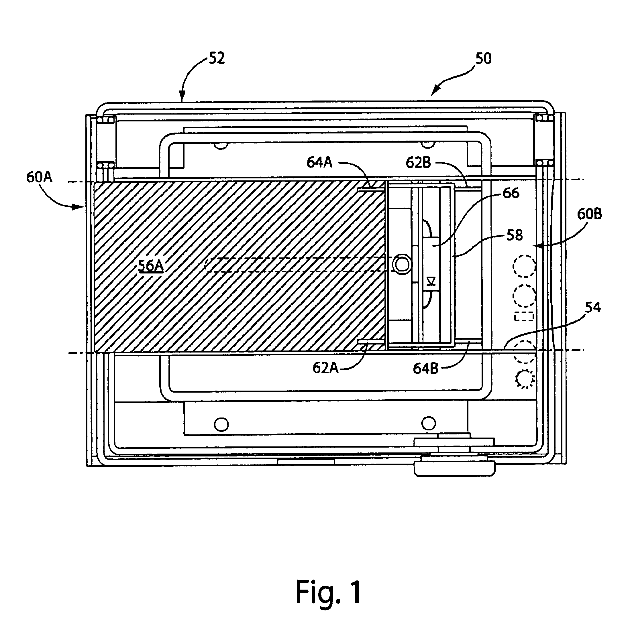
[0015]As shown in the embodiment 50 in FIG. 1, the equipment 52 housing has a battery tunnel 54 as a battery chamber to receive batteries, e.g. battery 56 therein to be received by and connected to a battery connector 58. The first battery 56 is received through a tunnel opening 60A on one side of the equipment 52. The battery connector 58 is retained within the tunnel 54 and slidable therein to permit the tail end of the battery 56 to be included within the equipment 52 housing. The battery connector 58 includes connectors positive and negative connectors 62A and 64A for mating with connections at the head end of the first battery, and positive and negative connectors 62B and 64B for mating with connections at the head end of the second battery (not shown here) which ele...


PUM


Abstract

A battery changing system having a battery chamber housing a first battery connected to a circuit, and receives a second, replacement battery which becomes connected to the circuit and displaces the first battery from the battery chamber as the second battery is being inserted, maintaining continuity of power to the circuit. Embodiments include a system which displaces the battery from the same side or opening in which the replacement battery is inserted, and a system which displaces the battery from another opening in the battery chamber.

Description

FIELD OF THE INVENTION[0001]This invention battery power systems adapted to continuously power a connected system for uninterrupted service even as the batteries are changed.BACKGROUND OF THE INVENTION[0002]There have been other non-interruptible systems developed, which use either a separate battery or capacitor to operate the system while the batteries are being changed. These systems work, they are either awkward or somewhat limited in use for use with high current draw systems.[0003]The most common non-interruptible battery exchange system in use today uses a high capacity capacitor which when charged will operate the system for the time it takes to change the battery. The problem is that these capacitors have limited storage capability, and therefore are limited in use with high draw system. Items such as computers (laptops) usually go into a sleep mode when this function is used to minimize the current draw.[0004]Another technique is to use a secondary battery to perform the f...

Claims


Application Information

Patent Timeline
IPC IPC(8): H01M10/42H01M2/10H01M10/48
CPCH01M2/1066Y02E60/10H01M50/209
Inventor PLUMADORE, JOHN DAVID
Owner VERMONT MEDICAL
Learn More