Method of fabricating microelectromechanical systems and devices having trench isolated contacts

a microelectromechanical and trench isolation technology, applied in the direction of fluid speed measurement, acceleration measurement using interia forces, instruments, etc., can solve the problems of mechanical structures that are difficult to cost effectively integrate with high-performance integrated circuitry on the same substrate, and high-performance integrated circuitry that is difficult to cost effectively integrate with high-performance circuitry,

Inactive Publication Date: 2005-08-30
ROBERT BOSCH GMBH
View PDF201 Cites 181 Cited by
  • Summary
  • Abstract
  • Description
  • Claims
  • Application Information

AI Technical Summary

Problems solved by technology

MEMS that employ a hermetically sealed metal container or a bonded semiconductor or glass-like substrate to protect the mechanical structures tend to be difficult to cost effectively integrate with high performance integrated circuitry on the same substrate.
In this regard, the additional processing required to integrate the high performance integrated circuitry, tends to either damage or destroy the mechanical structures.
Further, such an oxide is often formed or deposited in a manner that provides poor coverage of those areas where the underlying surface(s) exhibit significant spatial transitions.
In addition, a conventional oxide (deposited using conventional techniques) often provides an insufficient vacuum where a vacuum is desired as the environment in which the mechanical structures are encapsulated and designed to operate.

Method used


Image

  • Method of fabricating microelectromechanical systems and devices having trench isolated contacts
  • Method of fabricating microelectromechanical systems and devices having trench isolated contacts
  • Method of fabricating microelectromechanical systems and devices having trench isolated contacts

Examples


Embodiment Construction

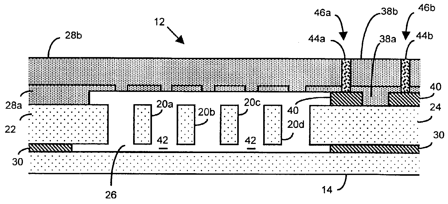
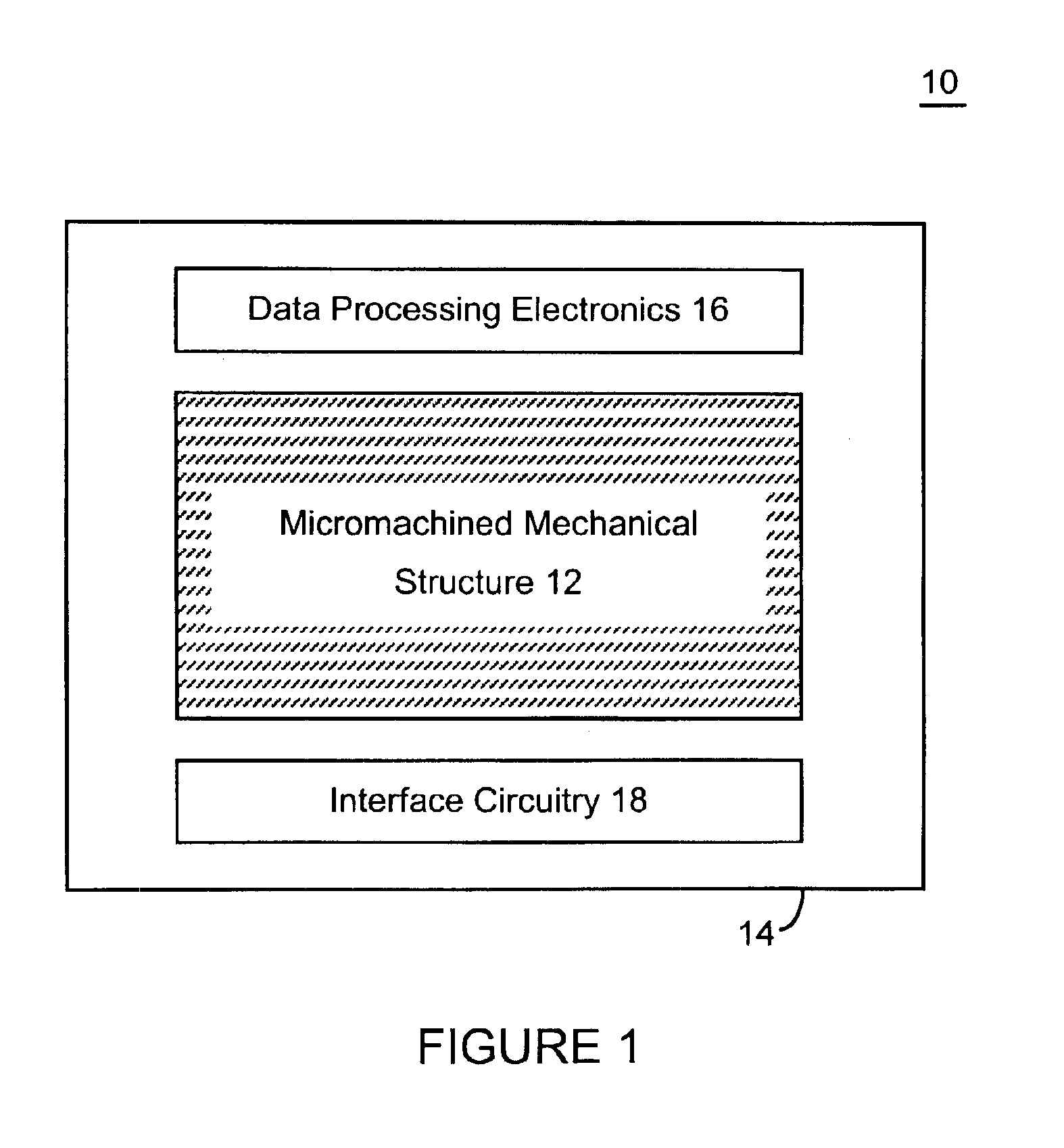
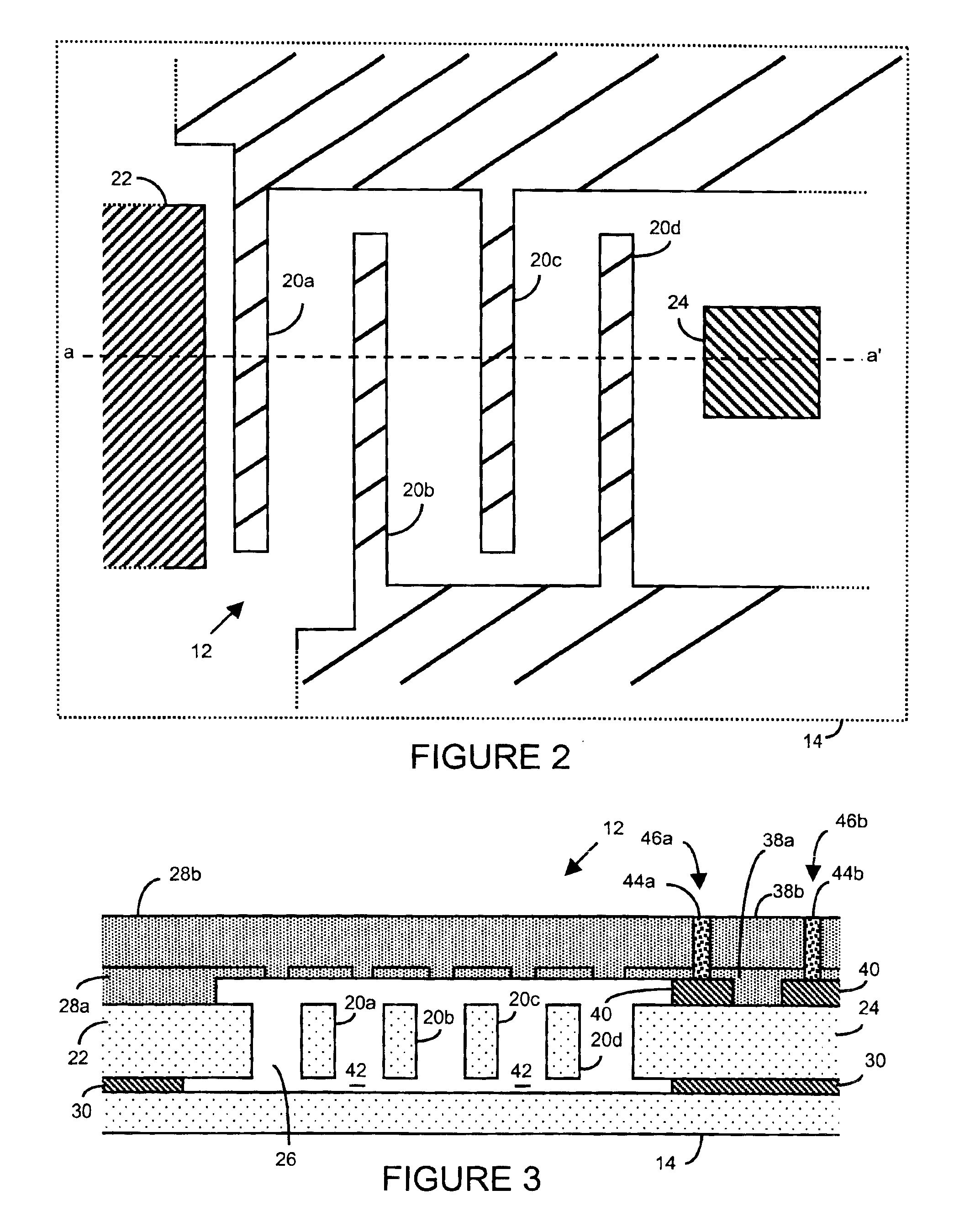
[0040]There are many inventions described and illustrated herein. In one aspect, the present invention is directed to a MEMS device, and technique of fabricating or manufacturing a MEMS device, having mechanical structures encapsulated in a chamber prior to final packaging and / or completion of the device. The material that encapsulates the mechanical structures may include one or more of the following attributes: low tensile stress, good step coverage, maintains integrity when subjected to subsequent processing, does not significantly and / or adversely affect the performance characteristics of the mechanical structures (if coated with the material during its deposition, formation and / or growth) within the chamber, maintains designed, appropriate and / or suitable encapsulation attributes over operating conditions and / or time, and / or facilitates integration with high-performance integrated circuits. In one embodiment, the mechanical structures are encapsulated by a semiconductor materia...


PUM


Abstract

There are many inventions described and illustrated herein. In one aspect, the present invention is directed to a MEMS device, and technique of fabricating or manufacturing a MEMS device, having mechanical structures encapsulated in a chamber prior to final packaging and a contact area disposed at least partially outside the chamber. The contact area is electrically isolated from nearby electrically conducting regions by way of dielectric isolation trench that is disposed around the contact area. The material that encapsulates the mechanical structures, when deposited, includes one or more of the following attributes: low tensile stress, good step coverage, maintains its integrity when subjected to subsequent processing, does not significantly and / or adversely impact the performance characteristics of the mechanical structures in the chamber (if coated with the material during deposition), and / or facilitates integration with high-performance integrated circuits. In one embodiment, the material that encapsulates the mechanical structures is, for example, silicon (polycrystalline, amorphous or porous, whether doped or undoped), silicon carbide, silicon-germanium, germanium, or gallium-arsenide.

Description

BACKGROUND[0001]This invention relates to electromechanical systems and techniques for fabricating microelectromechanical and nanoelectromechanical systems; and more particularly, in one aspect, to fabricating or manufacturing microelectromechanical and nanoelectromechanical systems with high performance integrated circuits on a common substrate.[0002]Microelectromechanical systems (“MEMS”), for example, gyroscopes, resonators and accelerometers, utilize micromachining techniques (i.e., lithographic and other precision fabrication techniques) to reduce mechanical components to a scale that is generally comparable to microelectronics. MEMS typically include a mechanical structure fabricated from or on, for example, a silicon substrate using micromachining techniques.[0003]The mechanical structures are typically sealed in a chamber. The delicate mechanical structure may be sealed in, for example, a hermetically sealed metal container (for example, a TO-8 “can”, see, for example, U.S. ...

Claims


Application Information

Patent Timeline
Patent Type & Authority Patents(United States)
IPC IPC(8): B81B7/00
CPCB81C1/00301B81B2207/015B81B2207/095B81C2201/0176B81C2203/0136
Inventor PARTRIDGE, AARONLUTZ, MARKUSKRONMUELLER, SILVIA
Owner ROBERT BOSCH GMBH
Why Eureka
Try Eureka