Dual-band dual-polarized antenna array

a dual-polarized antenna and array technology, applied in the direction of polarised antenna unit combinations, individually energised antenna arrays, resonant antennas, etc., can solve the problems of increasing the environmental impact of installation, doubling the number of installed antennas, and difficult to make an array operate simultaneously at two different frequencies or wavelengths, so as to improve antenna performance. the effect o

Inactive Publication Date: 2005-08-30
COMMSCOPE TECH LLC
View PDF218 Cites 39 Cited by
  • Summary
  • Abstract
  • Description
  • Claims
  • Application Information

AI Technical Summary

Benefits of technology

[0002]The present invention refers generally to a new family of antenna arrays that are able to operate simultaneously at two different frequency bands, while featuring dual-polarization at both bands. The design is suitable for applications where the two bands are centered at two frequencies f1 and f2 such that the ratio between the larger frequency (f2) to the smaller frequency (f1) is f2 / f1<1.5. The dual-band dual-polarization feature is achieved mainly by means of the physical position of the antenna elements within the array. Also, some particular antenna elements are newly disclosed to enhance the antenna performance.

Problems solved by technology

Keeping a minimum size for the antenna set-up in a BTS becomes a major issue when taking into account that the growth on the service demands forces operators in increasing the number of BTS, which is starting to produce a significant visual and environmental impact on urban and rural landscapes.
The problem becomes particularly significant when the operator has to provide both 2G and 3G services, because since both kinds of services operate at different frequency bands the deployment of both networks using conventional single-band antennas implies doubling the number of installed antennas and increasing the environmental impact of the installation.
The development of multiband antennas and antenna arrays is one of the main engineering challenges in the antenna field.
Due to this very simple principle, it is very difficult to make an array to operate simultaneously at two different frequencies or wavelengths, because is difficult to make the antenna element geometry to match in size two different wavelengths and similarly, it is difficult to find an spatial arranging of the antenna elements that meets the constraints of both wavelengths at the same time.
Said LPDA arrays where based on a non-uniform spacing of dipole elements of different sizes and were designed to cover a wide range of frequencies, however due their moderate gain (10 dBi) these designs have a restricted range of application and would not be suitable for applications such as for instance cellular services, where a higher gain (above 16 dBi) is required.
Also, neither the horizontal beamwidth (too narrow for BTS) nor the polarization and mechanical structure of said LPDA antennas match the requirements for BTS.
The general scope of that patent does not match the requirements of some particular applications.
Also, that solution is not necessarily cost-effective when an independent electrical down-tilt is required for each band.
The inconvenient of these antenna configurations are the size of the whole package (with up to 30 cm wide they are typically twice as much the size of a single antenna) and the pattern distortion due to the coupling between antennas.
However, such solutions are not suitable if an independent and different down-tilt is required for each band, which is something that can be easily solved according to the present invention.

Method used


Image

  • Dual-band dual-polarized antenna array
  • Dual-band dual-polarized antenna array
  • Dual-band dual-polarized antenna array

Examples


Embodiment Construction

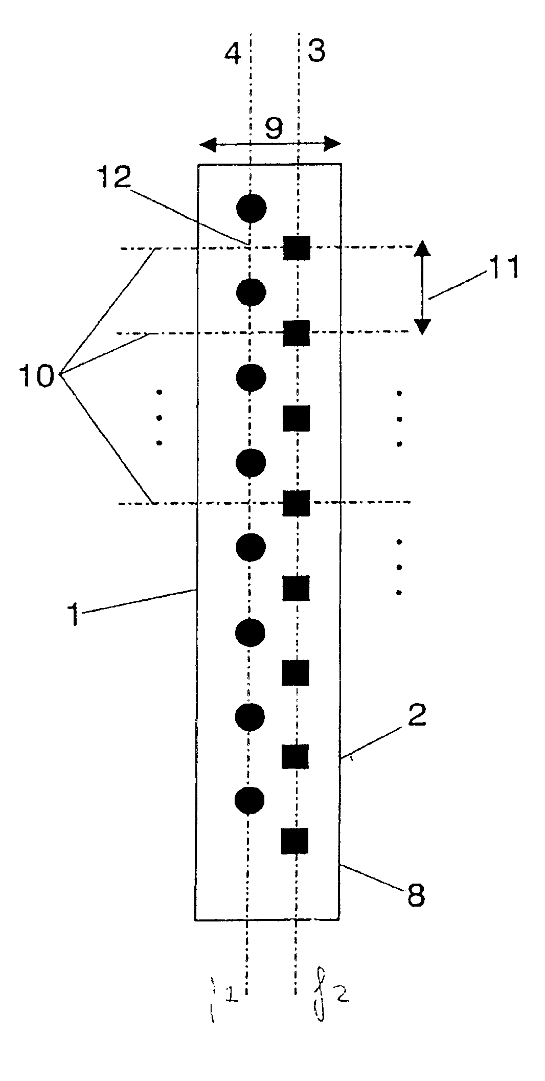
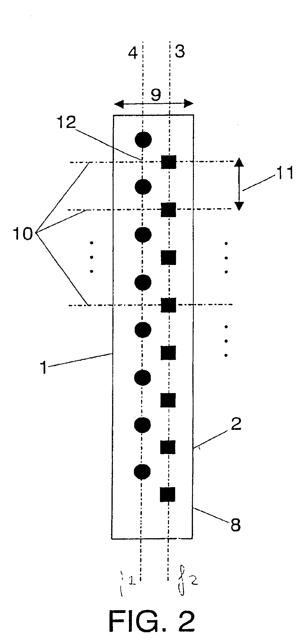
[0022]An scheme of the basic layout for the spatial arranging (interleaving) of the antenna elements is shown in FIG. 2. The solid dots (1) display the positions of the elements for the lower frequency f1, while the squares (2) display the positions for the antenna elements for the upper frequency f2. Antenna elements for the higher frequency band f2 are aligned along a vertical axis (3) with the desired spacing between elements (11). Said spacing is slightly smaller than a full-wavelength (typically below 98% the size of the shorter wavelength) for a maximum gain, although it can be readily seen that the spacing can be made shorter depending on the application. A second vertical column of elements for the lower frequency band f1 is aligned along a second vertical axis (4) placed next to said first axis (3) and substantially parallel to it. In the particular arrangement of FIG. 2 low-frequency elements are placed along the left axis (4) while high-frequency elements are place along ...


PUM


Abstract

The present invention refers generally to a new family of antenna arrays that are able to operate simultaneously at two different frequency bands, while featuring dual-polarization at both bands. The design is suitable for applications where the two bands are centered at two frequencies f1 and f2 such that the ratio between the larger frequency (f2) to the smaller frequency (f1) is f2 / f1<1.5. The dual-band dual-polarization feature is achieved mainly by means of the physical position of the antenna elements within the array. Also, some particular antenna elements are newly disclosed to enhance the antenna performance.

Description

[0001]This application is a continuation of international application number PCT EP01 / 04288 filed Apr. 16, 2001.OBJECT OF THE INVENTION[0002]The present invention refers generally to a new family of antenna arrays that are able to operate simultaneously at two different frequency bands, while featuring dual-polarization at both bands. The design is suitable for applications where the two bands are centered at two frequencies f1 and f2 such that the ratio between the larger frequency (f2) to the smaller frequency (f1) is f2 / f1<1.5. The dual-band dual-polarization feature is achieved mainly by means of the physical position of the antenna elements within the array. Also, some particular antenna elements are newly disclosed to enhance the antenna performance.BACKGROUND OF THE INVENTION[0003]The development of dual-band dual-polarization arrays is of most interest in for instance cellular telecommunication services. Both second generation (2G) cellular services, such as the European ...

Claims


Application Information

Patent Timeline
Patent Type & Authority Patents(United States)
IPC IPC(8): H01Q5/00H01Q1/24H01Q21/28H01Q21/00H01Q21/08H01Q1/38H01Q5/42H01Q21/24
CPCH01Q1/246H01Q1/38H01Q5/42H01Q21/24H01Q21/28H01Q21/08
Inventor PUENTE BALIARDA, CARLESANGUERA PROS, JAIMEBORJA BORAU, CARMEN
Owner COMMSCOPE TECH LLC
Why Eureka
Try Eureka