Liquid crystal display device of an in-plane switching mode including a black matrix layer
a liquid crystal display and in-plane switching technology, applied in the field of liquid crystal display devices of in-plane switching mode, can solve the problems of light leakage and reduced contrast properties, and achieve the effect of improving contrast properties and display properties
- Summary
- Abstract
- Description
- Claims
- Application Information
AI Technical Summary
Benefits of technology
Problems solved by technology
Method used
Image
Examples
first embodiment
[First Embodiment]
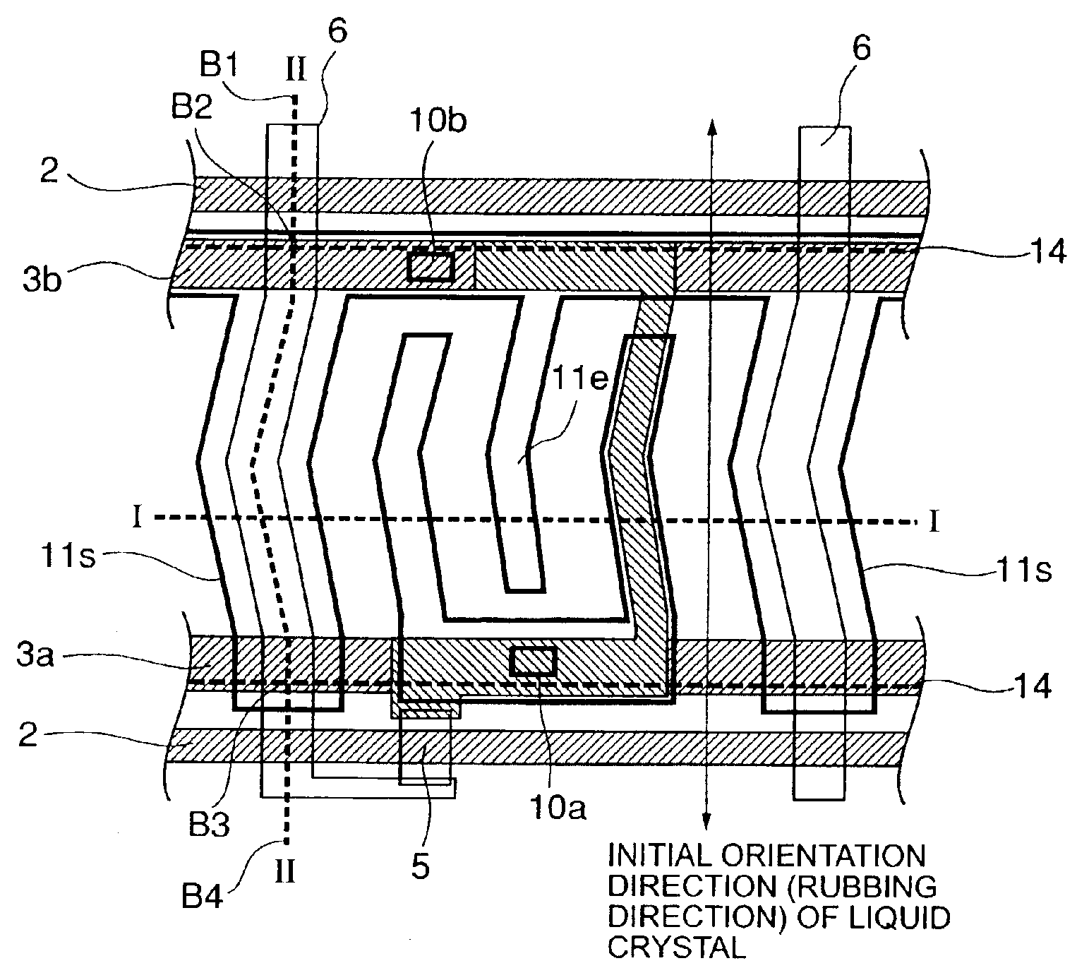
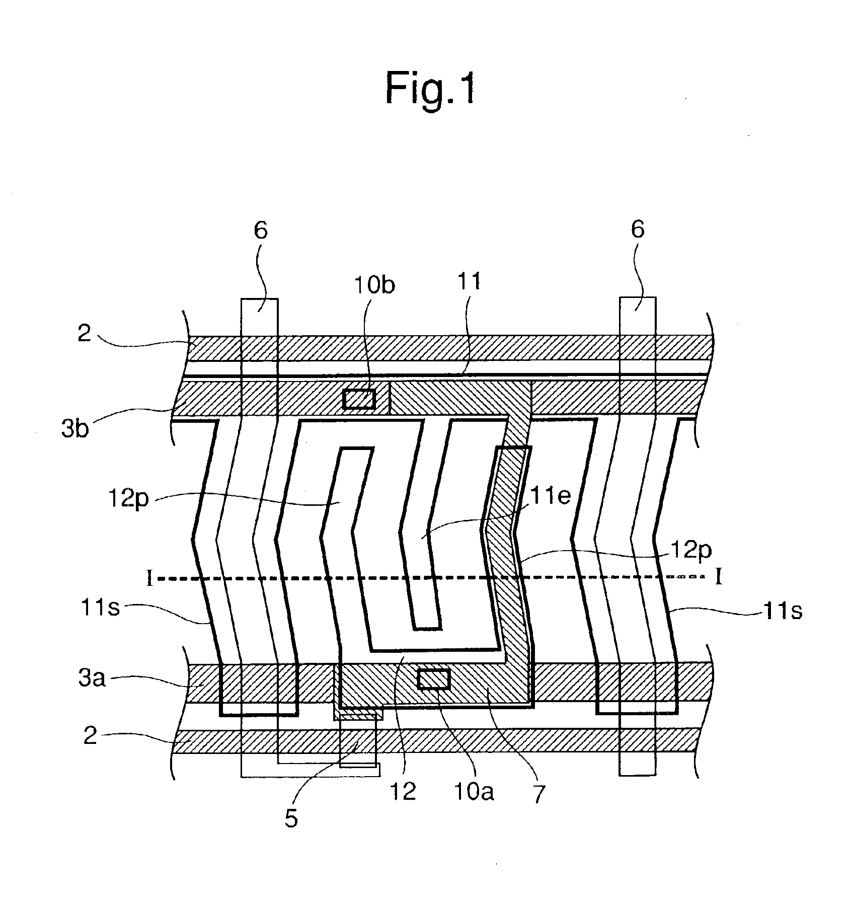
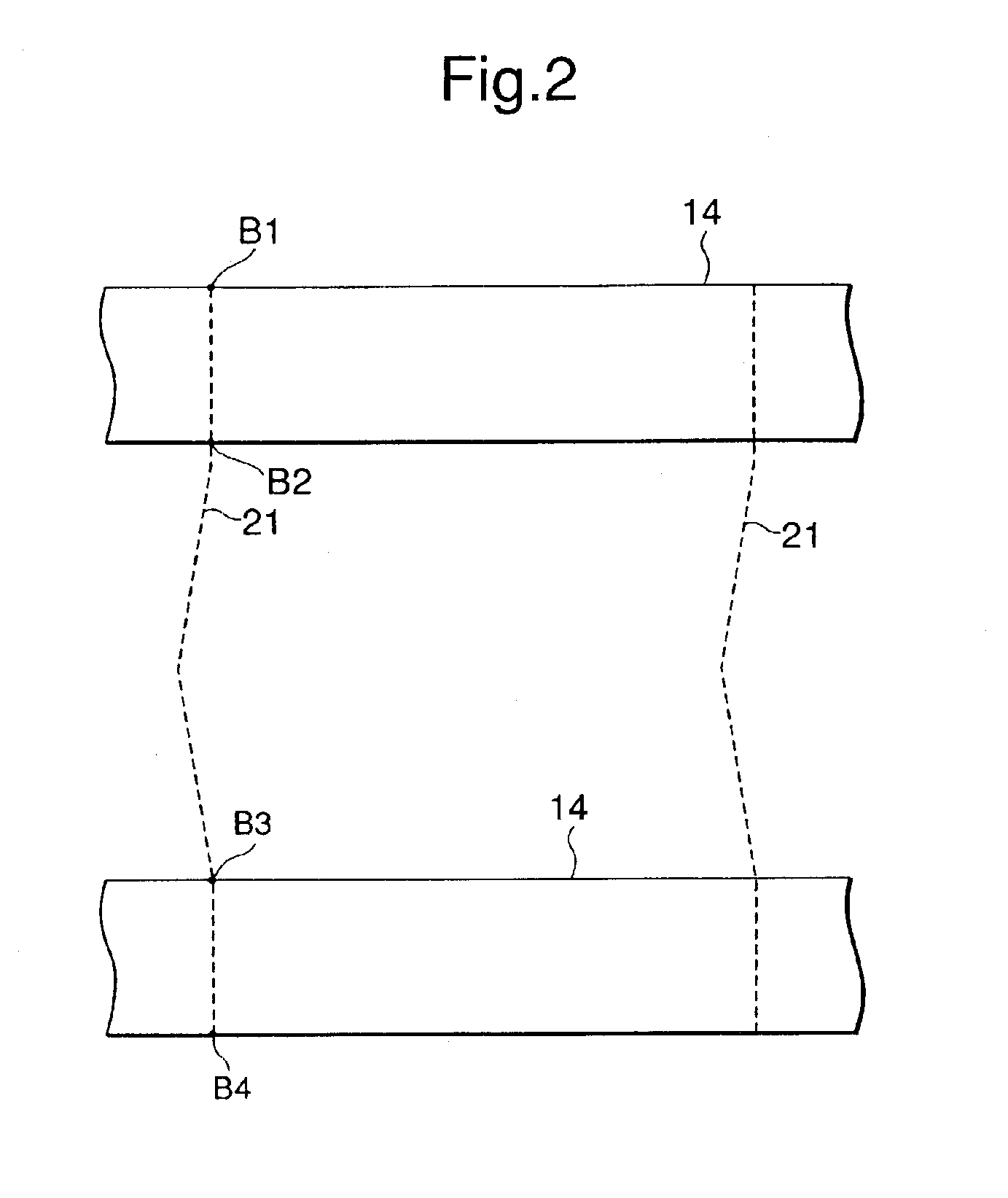
[0024]FIG. 1 is a top view showing an display region for one picture element portion of a TFT substrate for explaining a liquid crystal display device of a first embodiment of the present invention, FIG. 2 is a top view of a counter substrate for explaining the liquid crystal display device of the first embodiment of the present invention, and FIG. 3 is a top view showing almost one pixel of the liquid crystal display device of the first embodiment of the present invention which is constituted by having the TFT substrate shown in FIG. 1 and the counter substrate shown in FIG. 2 opposed to each other. FIG. 4 is a sectional view cut along the line II—II in FIG. 3.
[0025]The first embodiment is for the case where the present invention is adapted to a monochrome liquid crystal display device that holds a TFT substrate between a counter substrate 13 and a liquid crystal layer 16, and has a special characteristic in a black matrix layer 14 formed in a counter substrate 13...
second embodiment
[Second Embodiment]
[0051]Next, a liquid crystal display device of a second embodiment of the present invention will be described with reference to the drawings.
[0052]FIG. 6 is a top view showing a display region of almost one picture element portion of a liquid crystal display device of the second embodiment of the present invention. The present embodiment, similarly as the first embodiment, is the case where the present invention is adopted to a monochrome crystal display device which holds a liquid crystal layer 16 between a TFT substrate 1 and a counter substrate 13. Note that the detailed description of the constitutions which are the same as those of the first embodiment will be omitted by attaching the same reference numerals.
[0053]In the present embodiment, a signal line 6 is provided with a wide width portion 6W. This wide width portion 6W is a portion in which the signal line is curved. The constitution other than this is the same as that of the first embodiment. By providi...
third embodiment
[Third Embodiment]
[0055]Next, a liquid crystal display device of a third embodiment of the present invention will be described with reference to the drawings.
[0056]FIG. 7 is a top view of a TFT substrate for explaining the liquid crystal display device of the present embodiment, FIG. 8 is a top view of a counter substrate for explaining the liquid crystal display device of the present embodiment, FIG. 9 is a sectional view cut along the line I—I in FIG. 7 for explaining a relation among a signal line, a shield common electrode and a color superposing region of the present embodiment. Note that the description of the same constitutions as those of the first and second embodiments will be omitted by attaching the same reference numerals.
[0057]The present embodiment is the case where the present invention is adopted to a color liquid crystal display device comprising color layers of RGB on a counter substrate. The constitution of a TFT substrate side is the same as the TFT substrate 1 ...
PUM
 Abstract
Description
Claims
Application Information
 - R&D
- Intellectual Property
- Life Sciences
- Materials
- Tech Scout
- Unparalleled Data Quality
- Higher Quality Content
- 60% Fewer Hallucinations
Browse by: Latest US Patents, China's latest patents, Technical Efficacy Thesaurus, Application Domain, Technology Topic, Popular Technical Reports.
© 2025 PatSnap. All rights reserved.Legal|Privacy policy|Modern Slavery Act Transparency Statement|Sitemap|About US| Contact US: help@patsnap.com


