
Tire for a vehicle wheel capable of withstanding the load at low pressure or zero pressure

Inactive Publication Date: 2005-09-06
PIRELLI TYRE SPA
View PDF19 Cites 4 Cited by
  • Summary
  • Abstract
  • Description
  • Claims
  • Application Information

AI Technical Summary

Benefits of technology

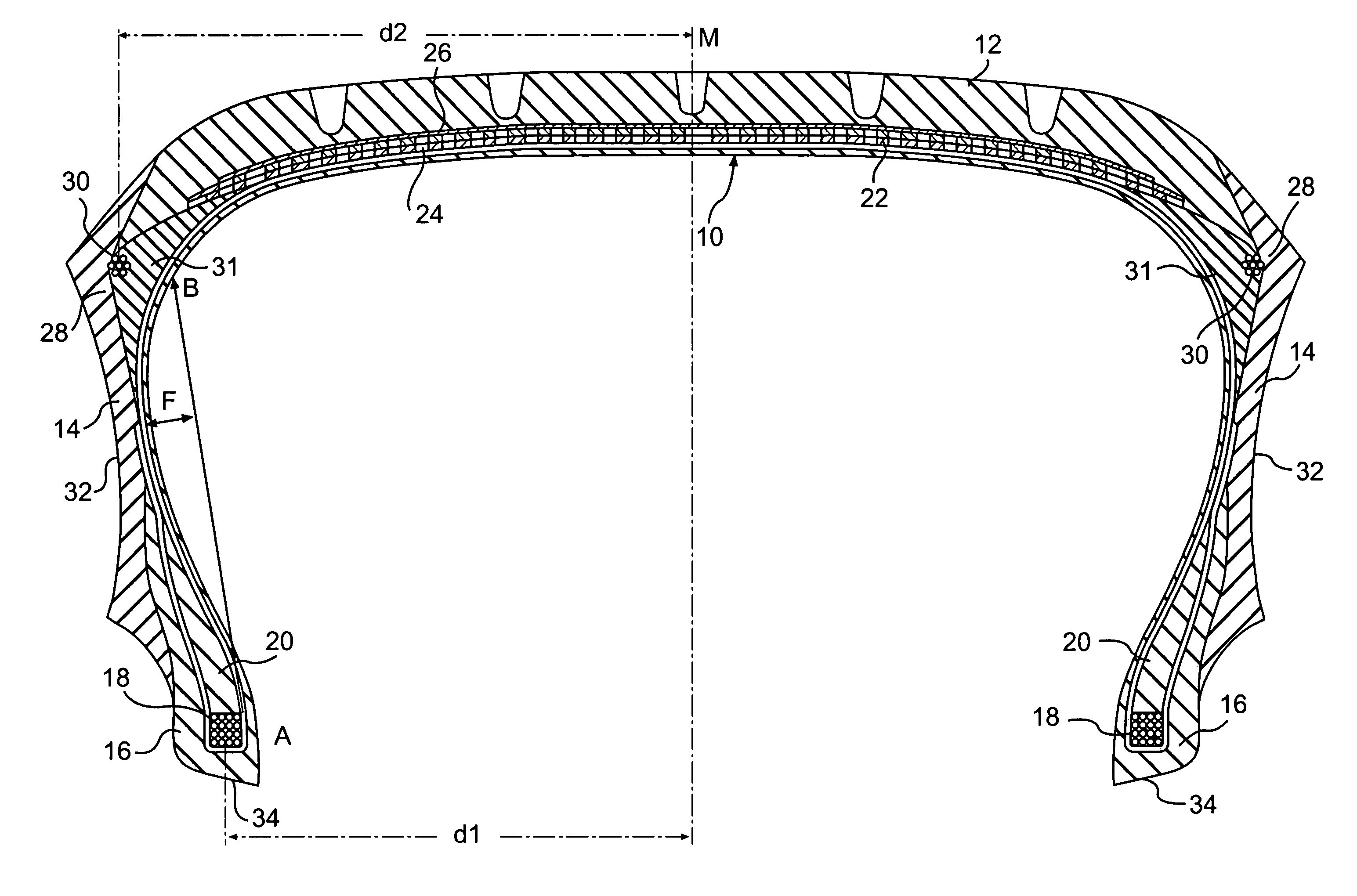
[0026]More specifically the present invention aims to provide a tyre suitable for flat travel classifiable in the category of tyres provided with structural reinforcing elements associated with the sidewalls of the tyre, so as to ensure a satisfactory performance in terms of behaviour, travel comfort and structural duration of the tyre, avoiding at the same time the risk of serious overheating and therefore thermo-chemical degradation of the tyres.
[0028]As may be understood from the detailed description of the preferred embodiments, the two structural elements form the load-bearing support of the tensile structure when there is no inflation pressure and, moreover, although being mainly subject to a compressive stress during flat travel, their composition (being made of metal or of a structural composite material as defined below) results in a negligible dissipation of energy.
[0033]This effect, moreover, is increased if the meridian curvature of the carcass ply line is kept as small as possible, since a high curvature of this profile would result in an increase in the flexing of the tyre for the same load during flat travel.
[0034]The smaller curvature of the ply line results in a greater lateral rigidity of the structure and therefore produces improved slip-angle characteristics under zero inflation pressure. The abovementioned characteristic features of the present invention also include the distance between the planes of the two structural reinforcing elements.
[0035]Indeed, this distance influences the performance of the tyre during flat travel in relation to the lateral thrusts, since, if the width of the belt is increased, thus positioning the two structural reinforcing elements at a considerable distance from each other, this performance improves.

Problems solved by technology

Without mentioning, for the sake of brevity, the proposed solutions based on the use of sealants of various types, mechanical devices which must be mounted on the rims, special rims, sponge-like inserts, etc., it is sufficient to consider the structures of tyres which are self-supporting, namely are able to withstand the load even under zero inflation pressure, in order to find in the prior art a large number of solutions which, however, hitherto have not produced satisfactory results.
The two cords in question do not have a structural function, but only that of facilitating folding of the ends of the belt during the tyre manufacturing process, as moreover confirmed by the suggested use of two nylon cords, which are entirely incapable of withstanding compressive forces and also very ineffective when subjected to tractional forces.
Between the sidewall and crown of the tyre, owing to the specific curvature of the sidewalls, an imperfect hinge is formed, said hinge, when subject to the flexural forces of normal travel, giving rise to the risk of rupture due to fatigue.
This consists of a complex structure with a high manufacturing cost.
In the case of the solutions proposed in the past with regard to self-supporting structures suitable for flat travel and involving the presence of elastomer structural elements, intense overheating occurs both during normal travel and, even more so, during flat travel.
This overheating in turn causes thermal / oxidative degradation of the materials, in particular the elastomer structural elements, and the consequent defects.
Although alternative solutions (previously mentioned) are known where the entire periphery of the tyre is reinforced and overheating is limited, the performance and comfort as well as duration of the tyre are greatly affected as a result during normal travel.

Method used


Image

  • Tire for a vehicle wheel capable of withstanding the load at low pressure or zero pressure
  • Tire for a vehicle wheel capable of withstanding the load at low pressure or zero pressure
  • Tire for a vehicle wheel capable of withstanding the load at low pressure or zero pressure

Examples


Embodiment Construction

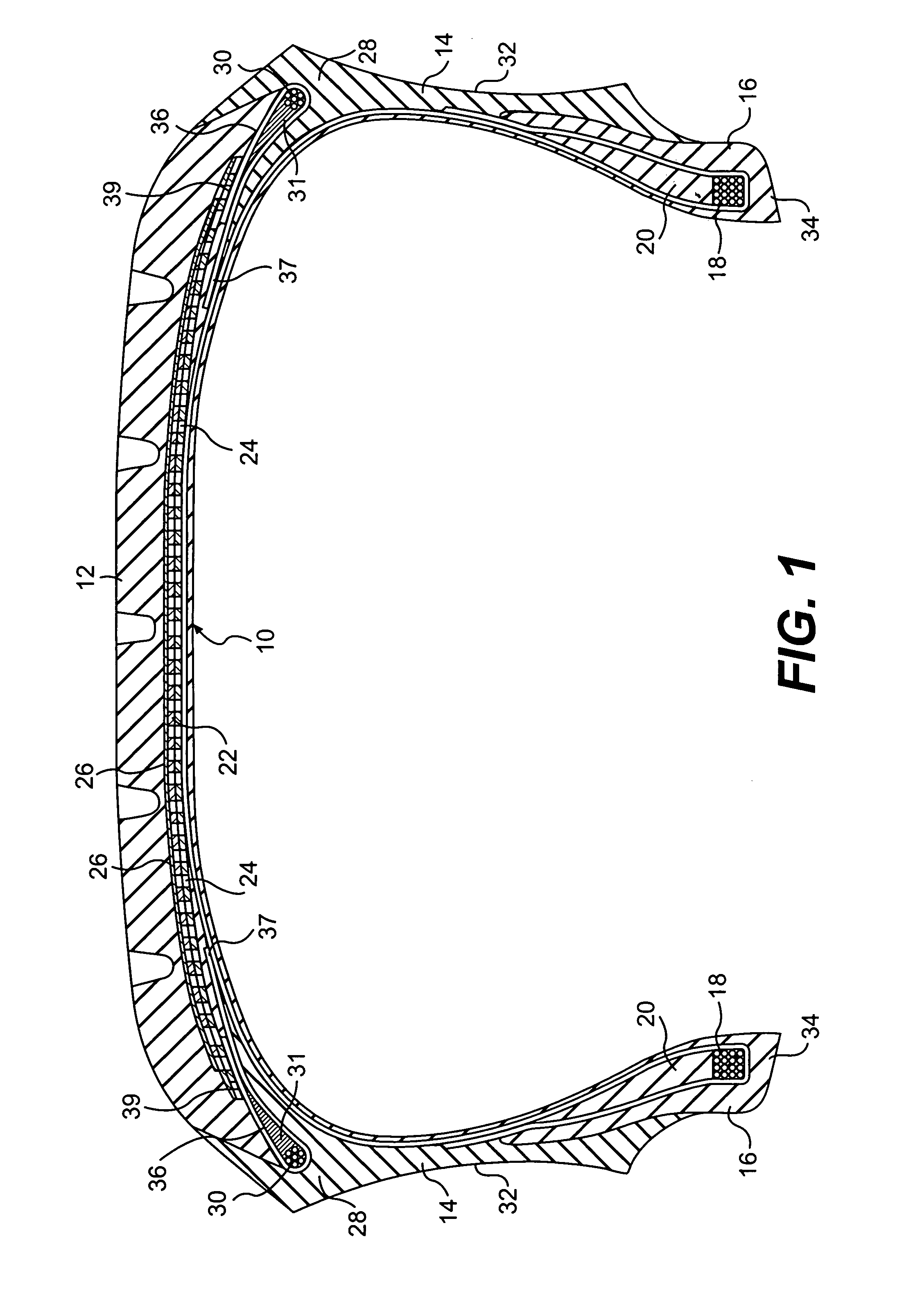
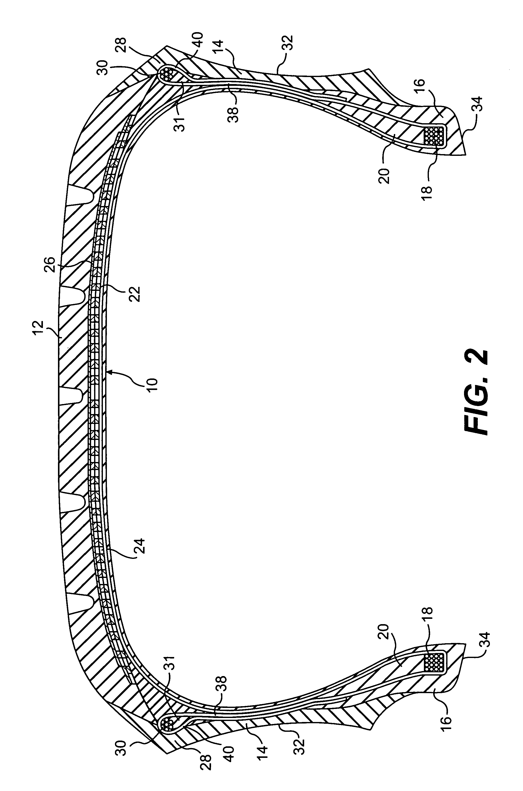
[0040]The tyre comprises a carcass 10, a tread band 12 which is located on the periphery of said carcass, a pair of sidewalls 14 which are axially opposite to each other and terminate in beads 16 reinforced by bead cores 18 and associated bead-filling elements 20, for securing said tyre onto a corresponding mounting rim. In the case of a radial carcass, the tyre also comprises a belt structure which is arranged between the carcass and tread band. More preferably, the tyre is of the type with a cross-section of low aspect ratio, for example, between 0.70 and 0.30, and even more preferably less than 0.65.

[0041]The carcass is reinforced in a traditional manner with one or more carcass plies 22 which are secured to said bead cores, while the belt structure comprises two or more belt strips 24 which are formed by sections of rubberised fabric incorporating metal cords, parallel with each other in each strip and intersecting with those of the adjacent strips, inclined preferably in a symm...


PUM


Abstract

A tire for a vehicle wheel, capable of withstanding the load at low pressure or zero pressure, includes a carcass, a crown, two axially opposed sidewalls, two bead cores, two compression-resistant annular reinforcing elements, and, optionally, a belt structure. The annular reinforcing elements are made of material having high rigidity and very low elastic hysteresis. Each annular reinforcing element is in or adjacent to a zone joining the crown to a sidewall and in a first plane parallel to an equatorial plane of the tire. Each bead core is in a second plane parallel to the equatorial plane. The distance between the first planes is greater than or equal to the distance between the second planes. A camber of an arc between a bead core and an intersection of a carcass ply line with a cylindrical surface passing through the reinforcing elements does not exceed 15% of the arc length.

Description

[0001]Applicants claim the right of priority under 35 U.S.C. § 119(e) based on prior-field copending provisional application No. 60 / 153,681, filed Sep. 14, 1999, in the U.S. Patent and Trademark Office.BACKGROUND OF THE INVENTION[0002]1. Field of the Invention[0003]The present invention relates motor vehicle wheels which is capable of withstanding the load even at low or zero pressure.[0004]2. Description of the Related Art[0005]It is well known that, since tyres were first developed, a large number of solutions have been proposed in an attempt to solve the problem relating to travel of said tyres in a deflated or—to use the technical term—“flat” condition. In fact this problem is important not only in the event of punctures during normal travel, but also with regard to military vehicles and therefore punctures caused for example by bullets.[0006]Without mentioning, for the sake of brevity, the proposed solutions based on the use of sealants of various types, mechanical devices whic...

Claims


Application Information

Patent Timeline
IPC IPC(8): B60C9/18B60C9/26B60C9/00B60C17/00B60C15/00B60C3/04
CPCB60C3/04B60C9/18B60C9/26B60C17/00B60C13/009Y10T152/1018Y10T152/10765Y10T152/10864Y10T152/10207
Inventor CUCCO, GIAN CARLOMISANI, PIEROVOLPI, ALESSANDRORIVA, GUIDO
Owner PIRELLI TYRE SPA
Learn More