Setting tool

a technology of setting tool and stapling tool, which is applied in the field of setting tool to achieve the effect of increasing the pressing for

Active Publication Date: 2005-09-06
HILTI AG
View PDF10 Cites 32 Cited by
  • Summary
  • Abstract
  • Description
  • Claims
  • Application Information

AI Technical Summary

Benefits of technology

[0008]These and other objects of the present invention, which will become apparent hereinafter, are achieved by providing a setting tool, the drive piston returning device of which includes an electromotive drive and a transmission for transmitting a motive actuation torque to the drive piston. The foregoing novel features of the present invention insure that the drive piston returns into its initial position reliably and without a need to apply an increased press-on force by the tool user. Further, the return of the drive piston in its initial position can be effected continuously and not only stepwise.
[0011]Advantageously, the transmission includes a gear unit which is formed in particular as a reducing gear and has its driving side connected with the electromotive drive, and its driven side connected with the at lease one friction wheel. The advantage of the combination friction wheel-gear unit consists in that the gear unit is not damaged by a rapid displacement of the drive piston during the setting process.
[0012]It is further advantageous when the one or several friction wheel(s) is / are elastically biased in a direction toward the piston drive shaft. With the friction wheel(s) being biased against the drive piston shaft, an elastic press-on force applied to the drive piston shaft provides for a better holding of the shaft and for compensation of any vibrations.
[0013]Advantageously, the one or several friction wheel(s) is / are provided with a support(s) acting in a setting direction and having a counter lock(s) for the drive piston. This insures sliding, during the setting process, of the drive piston shaft relative to the friction wheel(s) which remain or are held stationary. The displacement of the drive piston in the setting direction does not result in actuation of the gear unit or the electromotive drive, which substantially increases their service life.
[0014]By the provision of a free-running gear between the gear unit and the friction wheel(s), an action of the drive piston acceleration on the gear unit and the rotor of the electromotive drive during recoil, i.e., rapid return displacement of the drive piston, is prevented.
[0015]Advantageously, in the piston guide, there is provided a switch for detecting presence of the drive piston in its initial position. With the provision of the switch, the piston can be returned only over a required return path, which permits to minimize the amount of energy necessary for returning the drive piston to its initial position. The switch reacts very rapidly to the presence of the drive piston in its initial position, which provides for a greater setting frequency. Preferably, the switch is formed as a magnetoresistive sensor.

Problems solved by technology

This is a serious drawback, in particular when during the following setting process, e.g, a nail, a bolt, etc., having a greater length should be driven in a constructional component.

Method used


Image

  • Setting tool
  • Setting tool
  • Setting tool

Examples


Embodiment Construction

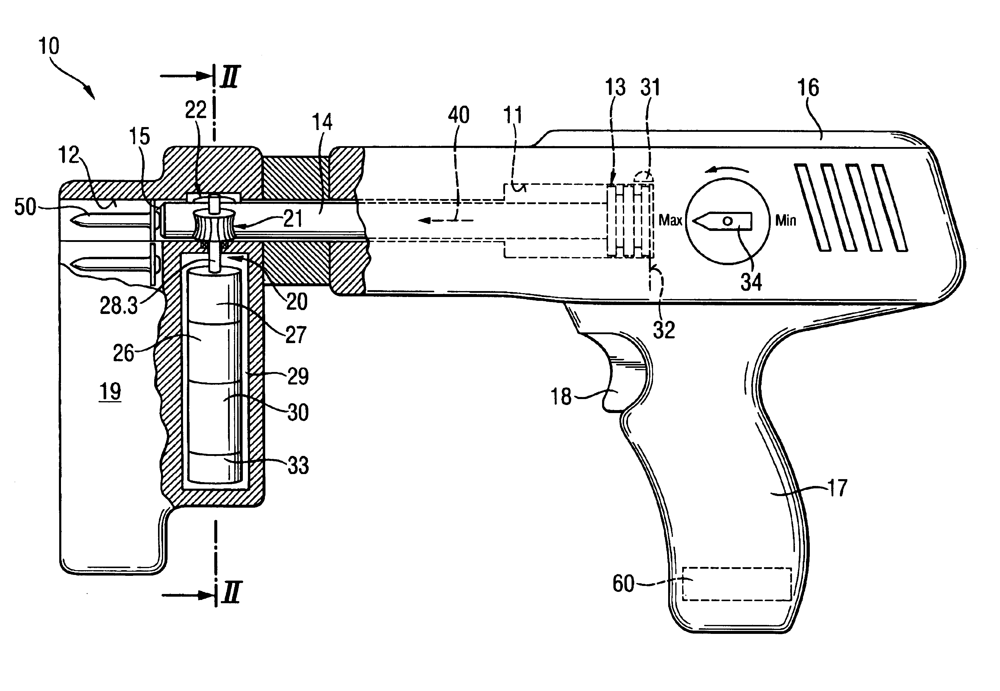
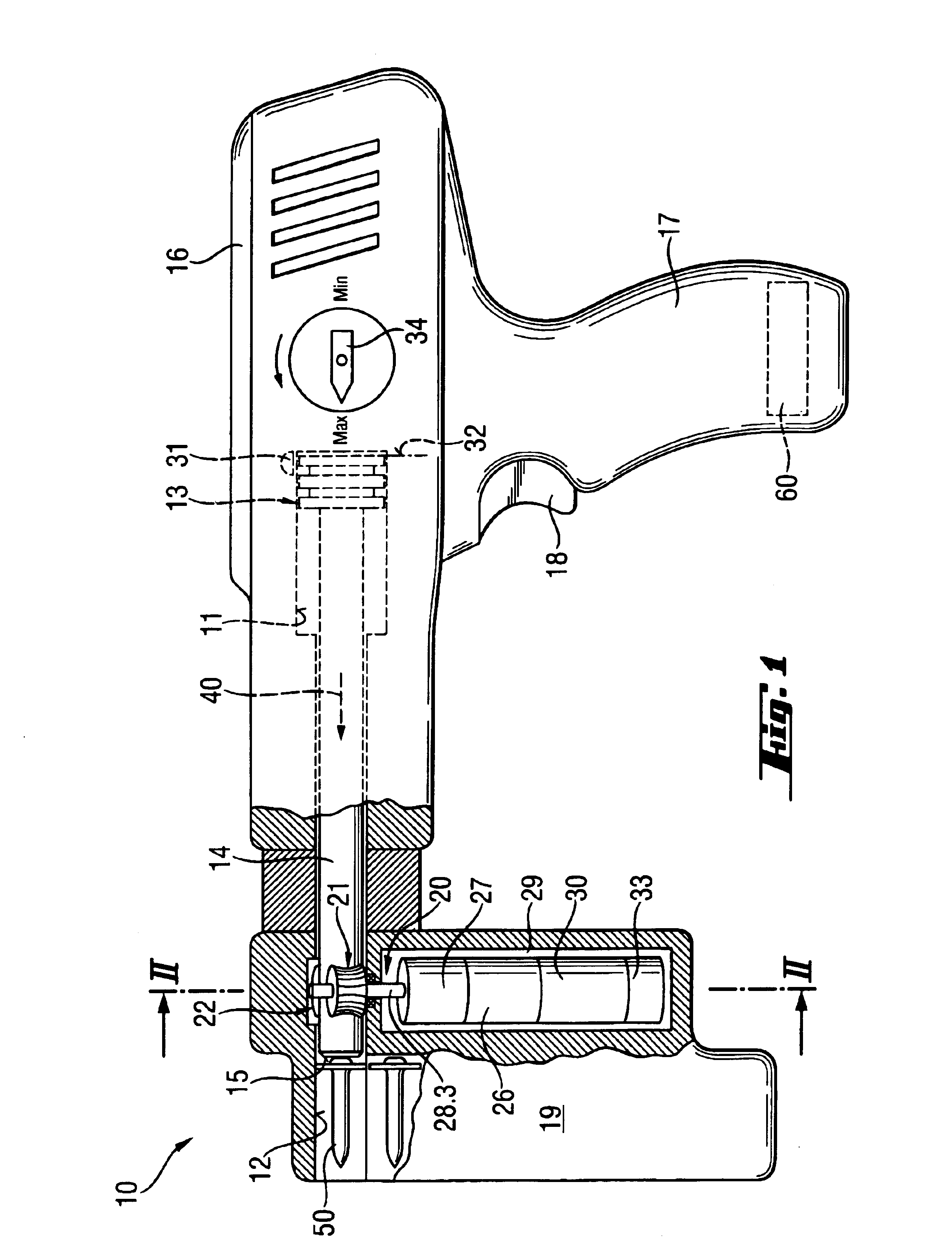
[0023]FIGS. 1-4 show a powder charge-operated embodiment of a setting tool according to the present invention. The setting tool 10, which is shown in the drawings, has a housing 16 with a handle 17 provided thereon. An actuation switch 18 for actuating the tool 10 is provided on the handle 17. In the interior of the housing 16, there is provided a piston guide 11 in which a drive piston 13 is axially displaceable. In FIG. 1, the drive piston 13 is shown in its initial position 32 in which it is completely located in the piston guide 11. The drive piston 13 has a piston shaft 14 a setting direction end 15 of which drives a fastening element 50 such as a bolt, nail or the like in a constructional component (not shown).

[0024]At the setting direction end of the piston guide 11, there is arranged a bolt guide 12 which includes a cylindrical hollow space through which the drive piston 13 is displaceable.

[0025]The setting direction is shown with arrow 40. Before start of a setting process,...


PUM


Abstract

A setting tool for driving in fastening elements includes a drive piston (13) displaceable in a piston guide (11) between its initial (32) and setting positions, and device for returning the drive piston (13) in its initial position upon completion of a setting process and having an electromotive drive (30) and a transmission (20) for transmitting a motive actuating torque to the drive piston (13).

Description

BACKGROUND OF THE INVENTION[0001]1. Field of the Invention[0002]The present invention relates to a setting tool for driving in fastening elements and including a piston guide, a drive piston displaceable in the piston guide between its initial position and its setting position in which the drive piston drives in a fastening element, and a device for returning the drive piston to its initial position after completion of a setting process.[0003]2. Description of the Prior Art[0004]Setting tools of the type described above can be operated with solid, gaseous, or liquid fuels or with compressed air. In combustion-operated setting tools, the setting or drive piston is driven by combustion gases. The setting piston drives a fastening element in a constructional component.[0005]Germani Publication DE 197 55 730 A1 discloses a setting tool having a piston guide in which a drive piston is displaceable. The piston guide itself is also axially displaceable in the tool housing. After completion...

Claims


Application Information

Patent Timeline
Patent Type & Authority Patents(United States)
IPC IPC(8): B25C1/14B25C1/00
CPCB25C1/14
Inventor EHMIG, GERHARDDITTRICH, TILO
Owner HILTI AG
Why Eureka
Try Eureka