
Flag or umbrella support pole

a technology of umbrellas and support poles, applied in the field of support poles, can solve the problems of cumbersome heavy weight, inability to easily translocate, and inability to provide a very stable attachment to the ground, and achieve the effect of stable and easy removal

Inactive Publication Date: 2005-09-06
CARLSON WARREN MERRILL
View PDF11 Cites 32 Cited by
  • Summary
  • Abstract
  • Description
  • Claims
  • Application Information

AI Technical Summary

Benefits of technology

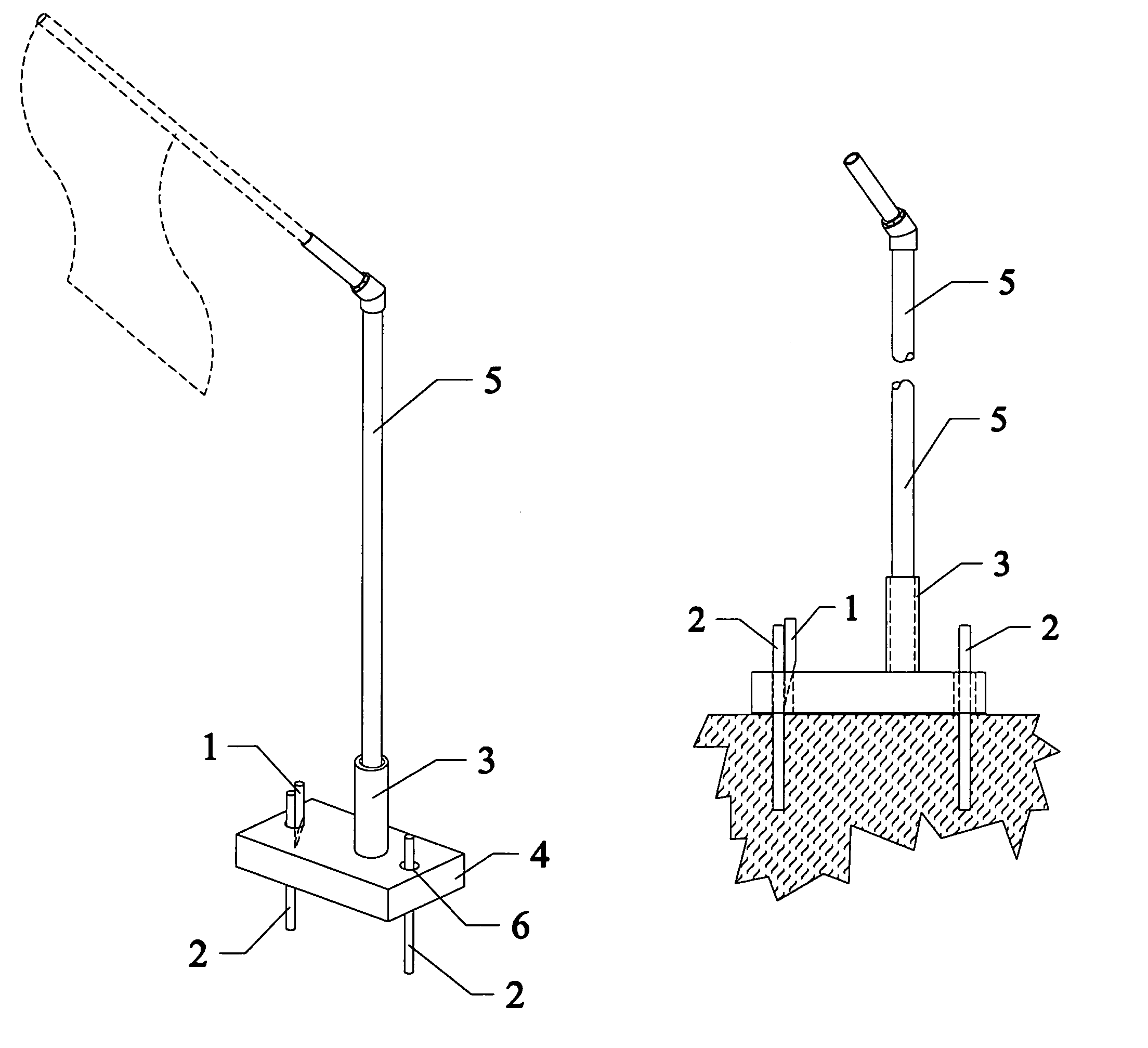
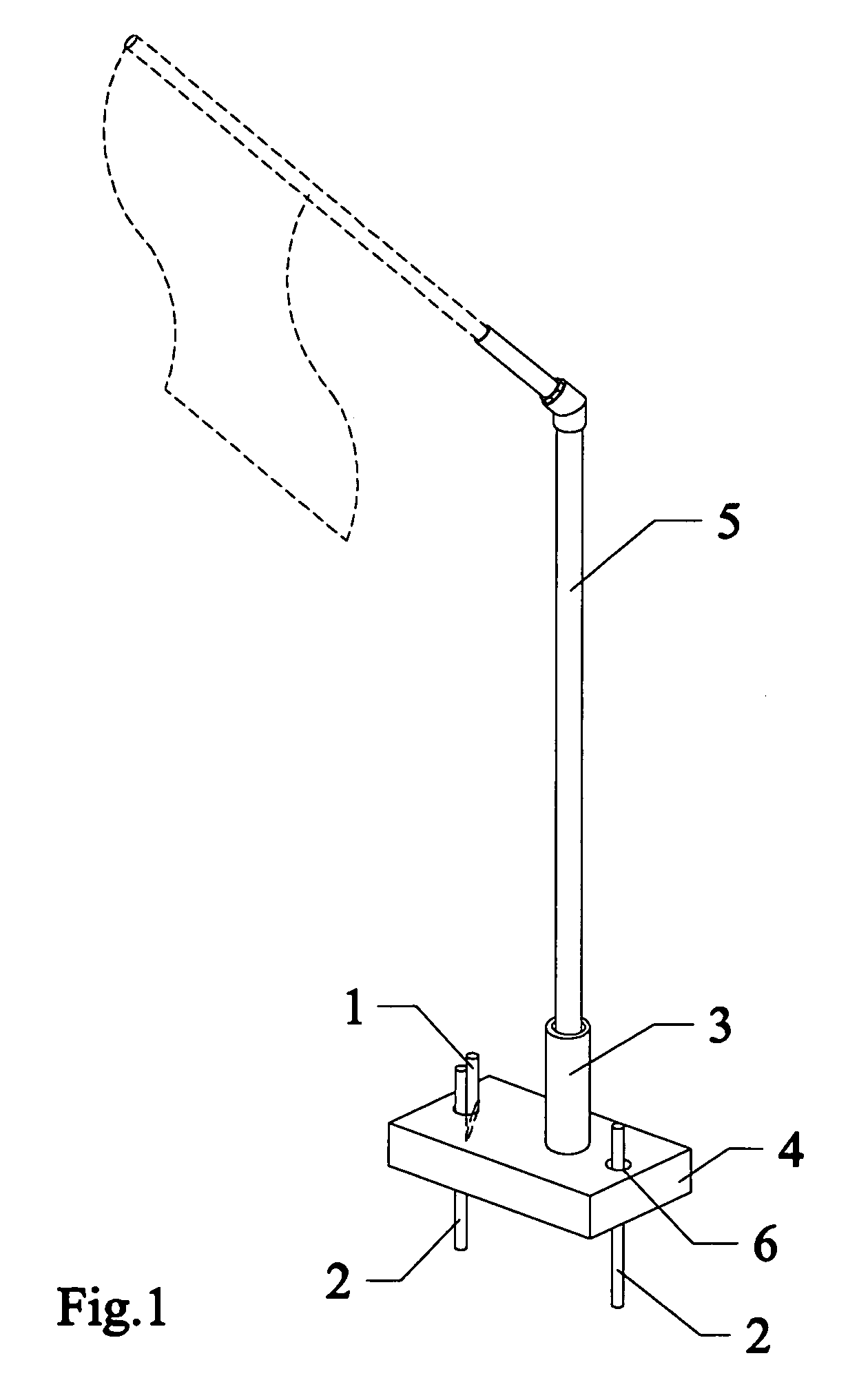
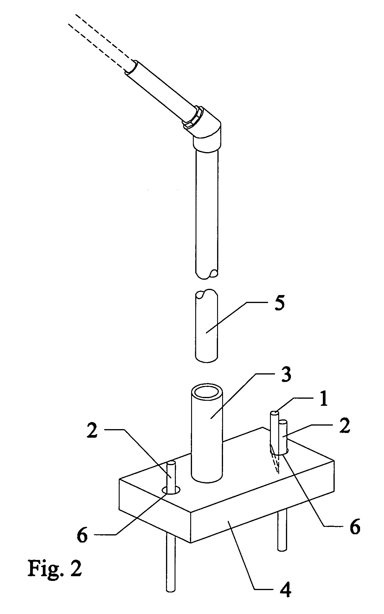
[0006]The present invention is a novel support pole design that is both stable and easily removable in an outdoor environment. The support pole is universally adaptable for use with flags, umbrellas, or other objects requiring support to an elevated position relative to the ground.

Problems solved by technology

The prior art support pole does not, however, provide a very stable attachment to the ground.
Such a weight does an admirable job of maintaining the support shaft in the desired upright orientation indoors, but outdoors the weight is unsuccessful in counteracting the torque imposed by a breeze and the support pole again falls to the ground.
If the weight is greatly increased, some success can be obtained, however a very heavy weight is cumbersome and not easily translocated as may be desired with a sun umbrella.

Method used


Image

  • Flag or umbrella support pole
  • Flag or umbrella support pole
  • Flag or umbrella support pole

Examples


Embodiment Construction

[0013]With reference to FIGS. 1 through 5, pole shaft 5 is removably coupled to the top surface of base 4 by means of coupling 3. FIG. 3 clearly shows that pole shaft 5 is not disposed through base 4. Rather, pole shaft 5 only sits in coupling 3. Coupling 3 is integrally attached to the top surface of base 4 by any means known in the art such as gluing, welding, threading, or forming. Shaft 5 may be of any cross sectional geometry, but typically shaft 5 is cylindrical in geometry with a cross sectional diameter in the range of about one and about three inches. Shaft 5 may include an umbrella or a flag at one end distal to coupling 3.

[0014]Coupling 3 may attach to shaft 5 by providing a threaded female socket on coupling 3 that is complementary to a threaded male end of shaft 5. Alternatively, coupling 3 may provide a simple, smooth female socket of inner diameter that is the same as the outer diameter of lower end of smooth shaft 5. In this alternate embodiment, the male end of shaf...


PUM


Abstract

A novel support pole design that is both stable and easily removable in an outdoor environment. The support pole is universally adaptable for use with flags, umbrellas, or other objects requiring support to an elevated position relative to the ground. A key feature of the present invention is the means that anchors the present invention to the ground. This means includes a small locking pin that maintains a large flat base in close coupling with the ground.

Description

BACKGROUND OF THE INVENTION[0001]1. Field of the Invention[0002]The present invention relates to the field of support poles or similar devices used for the display of flag-like objects or umbrellas in an outdoor environment.[0003]2. Description of the Prior Art[0004]It is well known in the prior art to use a pole or other extension in order to display a decorative object, such as a flag, or, alternatively, to provide a support means for an elevated object such as a sun umbrella. The simplest of such forms is no more than a straight shaft that is attached to the flag or umbrella at a first, upper end by mechanical means such as a threaded coupling, ropes, or the like. The second, lower end of the straight shaft is driven into the ground and held in place by the rigidity of the ground surrounding the shaft. This second end may taper to a point in order to facilitate entry into the ground. The prior art support pole does not, however, provide a very stable attachment to the ground. Eve...

Claims


Application Information

Patent Timeline
IPC IPC(8): G09F17/00
CPCG09F17/00G09F2017/0066
Inventor CARLSON, WARREN MERRILL
Owner CARLSON WARREN MERRILL
Learn More