Closely coupled exhaust aftertreatment system for an internal combustion engine having twin turbochargers

an exhaust aftertreatment and turbocharger technology, which is applied in the direction of engines, mechanical equipment, machines/engines, etc., can solve the problems of insufficient packaging space for scr, limited commercial application of lean-burn engines, and difficulty in ensuring the quality of the exhaust aftertreatment process

Inactive Publication Date: 2012-10-02
GM GLOBAL TECH OPERATIONS LLC +1
View PDF3 Cites 18 Cited by
  • Summary
  • Abstract
  • Description
  • Claims
  • Application Information

AI Technical Summary

Problems solved by technology

While a lean-burn engine has improved fuel economy, and lower combustion temperatures, which generally result in increased engine-out nitrogen oxides (NOX) emissions, commercial application of lean-burn engines is limited due to a lack of effective methods to remove sufficient NOX from the lean exhaust stream before it exits the tail pipe to meet regulations.
Reduction of NOX emissions from an exhaust stream including excess oxygen is a challenge for vehicle manufacturers.
While systems that employ SCR catalysts have been used for NOX reduction in exhaust gas flow streams having excess oxygen, packaging of the various catalysts has been problematic, particularly in relatively smaller vehicles having relatively shorter wheelbases, due the reduced space available to package the desired combinations of catalysts.
While this arrangement is desirable, there is generally not enough room to package the SCR last while also providing the needed mixing length for conversion of the injected urea into ammonia, particularly if the system also employs one or more additional exhaust treatment devices for the reduction of NOX or oxidation or reduction of other exhaust constituents, including carbon monoxide (CO), various hydrocarbons (HC), particulate matter (PM) and the like.
Even where treatment devices are placed away from the engine to lower their operating temperature and improve the device operating life, there are frequently competing considerations, such as device regeneration, that require periodically elevating the device temperature by reheating, which generally employs fuel and reduces the engine and vehicle efficiency and reduces fuel economy.

Method used


Image

  • Closely coupled exhaust aftertreatment system for an internal combustion engine having twin turbochargers
  • Closely coupled exhaust aftertreatment system for an internal combustion engine having twin turbochargers
  • Closely coupled exhaust aftertreatment system for an internal combustion engine having twin turbochargers

Examples


Embodiment Construction

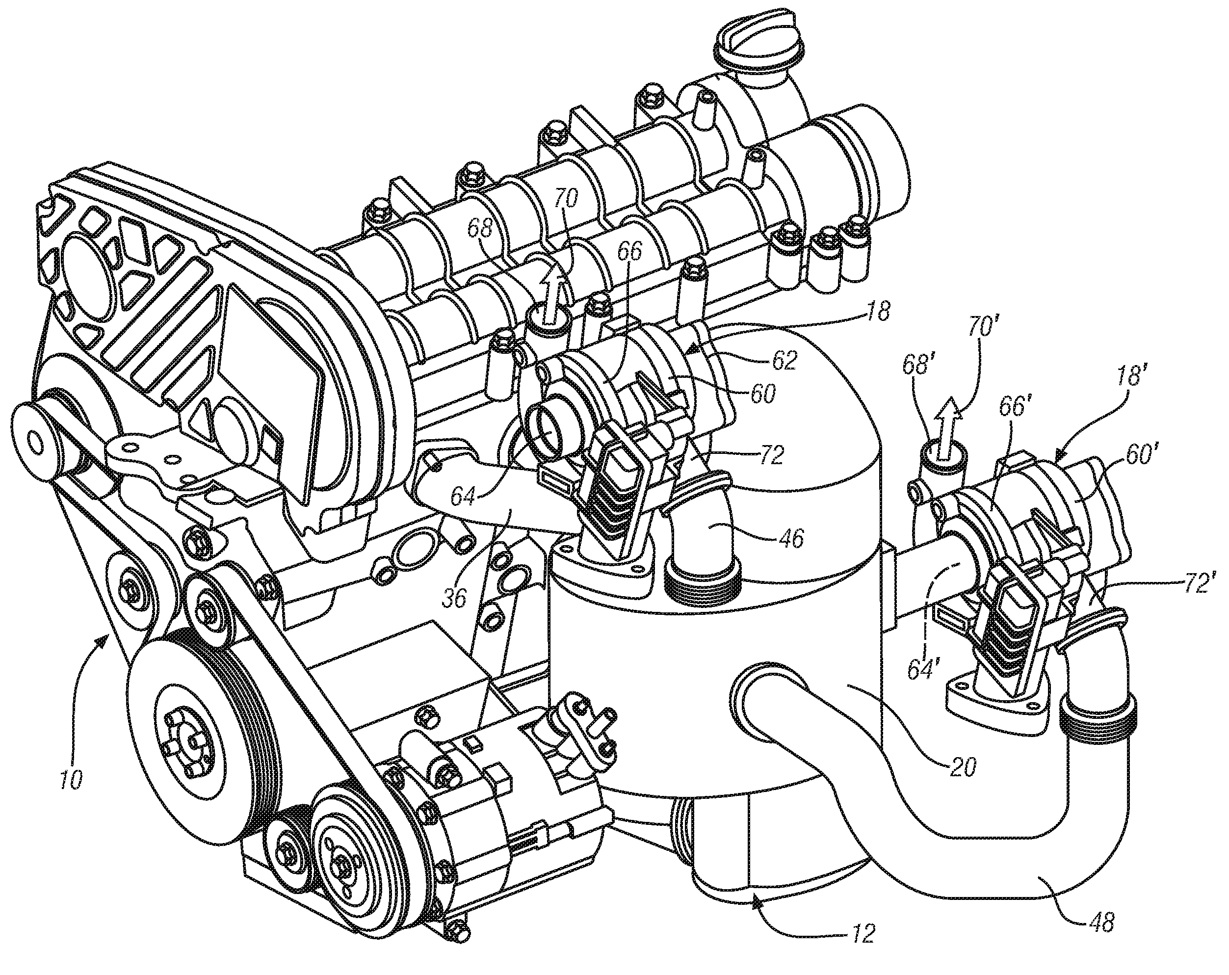
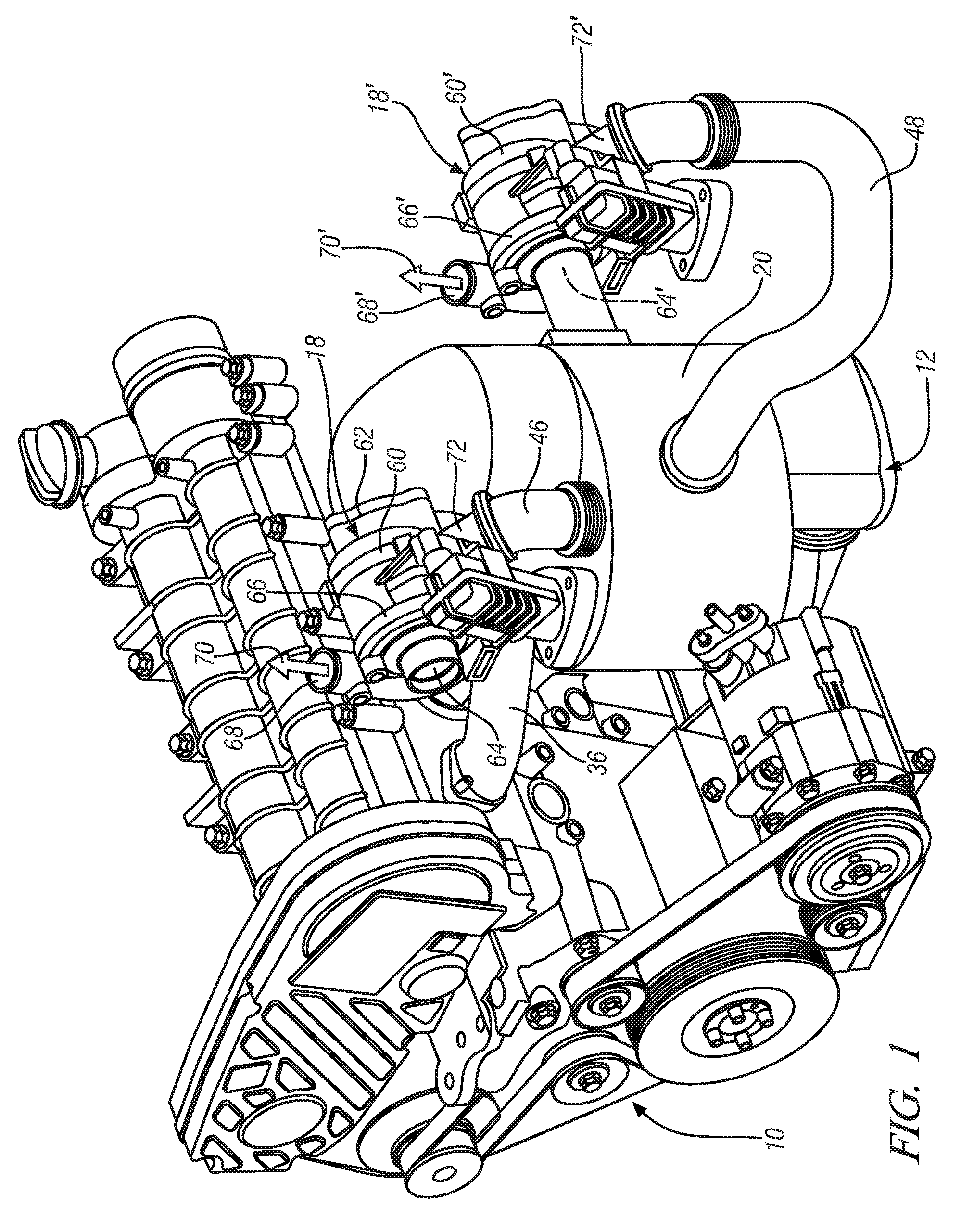
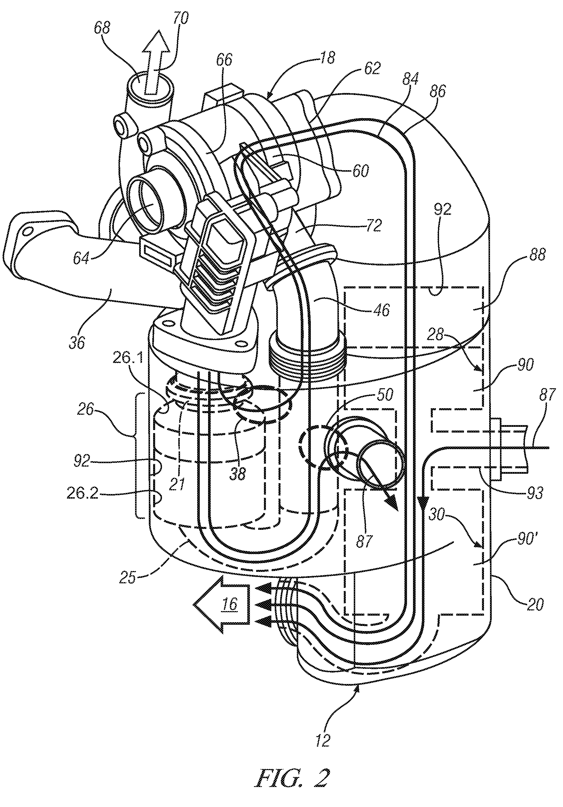
[0013]Referring now to FIGS. 1-5, an exemplary embodiment of an internal combustion engine 10 that is particularly suitable for use in many types of motorized vehicles 1, such as automobiles, light trucks, marine vehicles, ATVs and the like, as well as numerous fixed installation applications, such as generators, pumps and the like. Engine 10 is fluidly coupled to an exhaust aftertreatment system 12, including a plurality of fluidly coupled exhaust aftertreatment devices 14, for treating an exhaust gas flow 16 resulting from its operation. Exhaust aftertreatment system 12 is fluidly coupled to twin turbochargers, including first turbocharger 18 and second turbocharger 18′. In an exemplary embodiment, exhaust aftertreatment system 12 is configured to be used as a close-coupled system in that the exhaust aftertreatment devices 14 are housed in a single housing 20 that may be directly coupled to an exhaust port 24, or to an exhaust manifold 22 that is configured to receive the exhaust ...


PUM


Abstract

A closely-coupled exhaust aftertreatment system for an engine having twin turbochargers includes a first exhaust conduit comprising a first valve operable between first and second positions, the first promoting flow within the first conduit to an oxidation catalyst (OC), the second promoting flow within a second conduit; a third conduit is fluidly coupled to the OC outlet and includes a second valve operable between first and second positions, the first promoting flow within the third exhaust conduit to a particulate filter (PF), the second promoting flow through a fourth conduit to an inlet in the second conduit. A first turbocharger is coupled to the second exhaust conduit downstream of the inlet; an SCR catalyst is downstream of the first turbocharger to receive the flow therefrom and upstream of the PF to provide the flow thereto. A second turbocharger is coupled to the third exhaust conduit downstream of the second valve.

Description

FIELD OF THE INVENTION[0001]Exemplary embodiments of the present invention are related to exhaust aftertreatment systems, and, more specifically, to an exhaust aftertreatment system for lean-burn internal combustion engines and vehicles incorporating the same.BACKGROUND[0002]Internal combustion engines must meet various regulations for reduced emissions and improved fuel economy. One example of a way to improve fuel economy is to operate an engine at an air / fuel ratio that is lean (excess oxygen) of stoichiometry. Examples of lean-burn engines include compression-ignition (diesel) and lean-burn spark-ignition engines. While a lean-burn engine has improved fuel economy, and lower combustion temperatures, which generally result in increased engine-out nitrogen oxides (NOX) emissions, commercial application of lean-burn engines is limited due to a lack of effective methods to remove sufficient NOX from the lean exhaust stream before it exits the tail pipe to meet regulations.[0003]Redu...

Claims


Application Information

Patent Timeline
Patent Type & Authority Patents(United States)
IPC IPC(8): F01N5/04F01N3/10F01N3/02F01N3/00
CPCF01N3/021F01N3/2053F01N3/2066F01N13/0097F02B37/007F01N2410/00Y02T10/144Y02T10/16Y02T10/24Y02A50/20Y02T10/12
Inventor BENNET, DAVIDCOOPER, BRIANTHOMAS, HUNTLY W.WINDER, NICK
Owner GM GLOBAL TECH OPERATIONS LLC
Why Eureka
Try Eureka