Coordination control method for circulating fluidized bed generator set

A circulating fluidized bed and coordinated control technology, which is used in the control of generators, control systems, electrical components, etc., can solve problems such as disturbance, thermal inertia, and control difficulties, and achieve the effect of reducing PID operation links.

Active Publication Date: 2009-05-13
STATE GRID TIANJIN ELECTRIC POWER +1
View PDF0 Cites 19 Cited by
  • Summary
  • Abstract
  • Description
  • Claims
  • Application Information

AI Technical Summary

Problems solved by technology

[0004] With the advancement of science and technology, circulating fluidized bed boilers are gradually replacing traditional pulverized coal boilers due to their high combustion efficiency, low pollution, and wide fuel adaptability. The main differences between circulating fluidized bed boilers and pulverized coal boilers are: coal The fuel of the powder furnace burns quickly after entering the furnace, while the fuel of the circulating fluidized bed boiler is coal particles, which burn in layers after entering the furnace, and the unburned coal particles return to the furnace to continue burning through circulation, and the entire combustion time is longer , the heat capacity is much larger than that of the pulverized coal boiler, but it is precisely because the coal particles in the circulating fluidized bed boiler are cyclically burned that its combustion characteristics are pure delay and large inertia, especially its pure delay time occupies the entire combustion process. The proportion is relatively large. The combustion delay time of the traditional pulverized coal furnace is 4 to 6 minutes, while the combustion delay time of the circulating fluidized bed boiler is more than 16 to 22 minutes. If we continue to use the traditional direct energy balance method to control the circulating fluidization bed generator set, will bring a lot of disturbance
As the boiler capacity increases, the bed material increases, the thermal inertia also increases, and the control becomes more difficult

Method used


Image

  • Coordination control method for circulating fluidized bed generator set
  • Coordination control method for circulating fluidized bed generator set
  • Coordination control method for circulating fluidized bed generator set

Examples


Embodiment Construction

[0054] Below in conjunction with the examples, the present invention is further described, the following examples are illustrative, not limiting, and the protection scope of the present invention cannot be limited by the following examples.

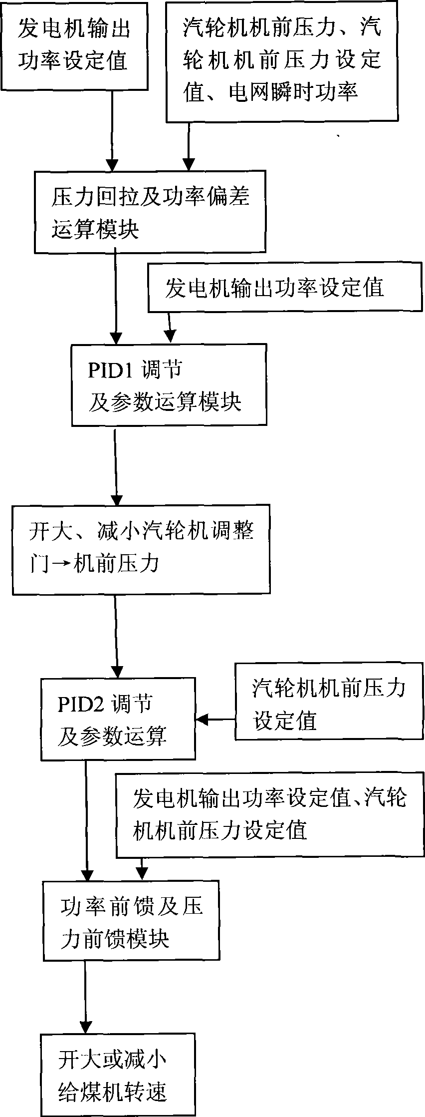
[0055] A coordinated control method for a circulating fluidized bed generator set, the steps of the coordinated control method are:

[0056] (1). Set the output power setting value of the generator and the pre-pressure setting value of the steam turbine, and the system switches from manual operation to automatic operation state;

[0057] (2). Detect and store the instantaneous power value of the grid and the pressure value before the steam turbine;

[0058] (3). Replace the set value of generator output power and the set value of the pre-machine pressure of the steam turbine with the stored instantaneous power value of the power grid and the pre-press value of the steam turbine respectively;

[0059] (4). The instantaneous power value of...


PUM


Abstract

The invention relates to a method for coordinating and controlling a generator set of a circulating fluidized bed. On the basis of the direct energy balance method, a two-stage PID operation link is canceled, a boiler and a steam turbine are regarded as a whole, a loop of a pressure pulling back and power deviation operation module is added, and the speed of actions of a control valve of the steam turbine is limited; a power feedforward module and a pressure feedforward module are added, and the variable quantity of a load point is moved forward, so as to compensate for the lagging deficiency of the boiler of the circulating fluidized bed; a Y1 polygonal function, a Y2 polygonal function, a Y3 polygonal function and a Y4 polygonal function are added, so that complex dynamic characteristics can be embodied in the polygonal functions; and a close coupling system is decomposed and then integrated, so that the response ability of the generator set is quicker and steadier. After the method is applied to the generator set of the circulating fluidized bed, the variable quantity of the deviation can be brought forward, and more importantly, the adjusting time of the boiler as a big lagging link is reduced.

Description

technical field [0001] The invention belongs to the technical field of generator set control, in particular to a coordinated control method for circulating fluidized bed generator sets. Background technique [0002] The normal supply of electricity is inseparable from power generation equipment, and power generation equipment is mainly composed of boilers, steam turbines, generators, auxiliary equipment and control equipment, among which the most commonly used boiler is pulverized coal furnace. The working principle of the generator set is: the raw coal enters the boiler through the coal feeder for combustion, and the heat generated by the combustion is absorbed by the circulating water in the boiler. When the temperature of the water exceeds the saturation temperature, it becomes water vapor, and the water vapor drives the steam turbine to rotate at a high speed. The closed coil of the generator cuts the magnetic force line under the action of the magnetic field to generate...

Claims


Application Information

Patent Timeline
Patent Type & Authority Applications(China)
IPC IPC(8): H02P9/00H02P9/04
Inventor 赵毅
Owner STATE GRID TIANJIN ELECTRIC POWER
Why Eureka
Try Eureka