Scroll compressor

a compressor and compressor technology, applied in the direction of machines/engines, couplings, liquid fuel engines, etc., can solve the problems of key vibration, vibration and noise, and the area where the above reaction force is imbalanced, so as to suppress the fluctuation of rotational torque and stable operation. , the effect of less torque fluctuation

Inactive Publication Date: 2005-09-06
DAIKIN IND LTD
View PDF16 Cites 4 Cited by
  • Summary
  • Abstract
  • Description
  • Claims
  • Application Information

AI Technical Summary

Benefits of technology

[0014]As described above, the rotational torque (T) occurring during the orbital revolution of the orbiting scroll (26) is the total of moments that are produced by various factors, including the moment produced by a gas force, and it increases or decreases in magnitude cyclically with one cycle that is equivalent to one orbital revolution of the orbiting scroll (26). And, in the present invention defined in the first aspect, the reaction force of gas compression and the inertia force of sliding movement of the Oldham coupling (39) produce an action to make the range of fluctuation of the total torque (T) smaller than that of the first rotational torque (T1) during the orbital revolution of the orbiting scroll (26). Accordingly, this can prevent the orbiting scroll (26) from rotating on its own axis in the reverse direction during the orbital revolution of the orbiting scroll (26). Thus, any vibration of the Oldham coupling (39) does not occur easily and the orbital revolution of the orbiting scroll (26) is made stable.
[0030]Further, according to the present invention defined in the sixth aspect, the range of fluctuation of the rotational torque (T) can be suppressed certainly in the asymmetric-volute structure in which the range of fluctuation of the rotation torque (T) tends to become great, and the occurring direction of the rotational torque (T) can be prevented from reversing. Further, the vibration and noise caused by the fluctuation of the rotational torque (T) of the scroll compressor having the asymmetric-volute structure can be suppressed certainly.

Problems solved by technology

In the asymmetric-volute structure, however, there may exist an area where the above reaction forces are imbalanced.
Accordingly, there was a problem that keys of the Oldham coupling shake in clearances in the key grooves of the hosing and the orbiting scroll, thereby producing a vibration and a noise.
However, even the symmetric-volute structure have also a risk that the vibration of key may occur due to the fluctuation of the rotational torque, and therefore a stable operation with less torque vibration should be desirable for the symmetric-volute structure as well.
In this case, however, there may be some possibility that design conditions, such as dimension or strength of wrap, or necessary compression characteristics, are not satisfied to the contrary.
Accordingly, in fact it was very difficult to design simply to suppress only the rotational torque of the orbiting scroll.

Method used


Image

  • Scroll compressor
  • Scroll compressor
  • Scroll compressor

Examples


Embodiment Construction

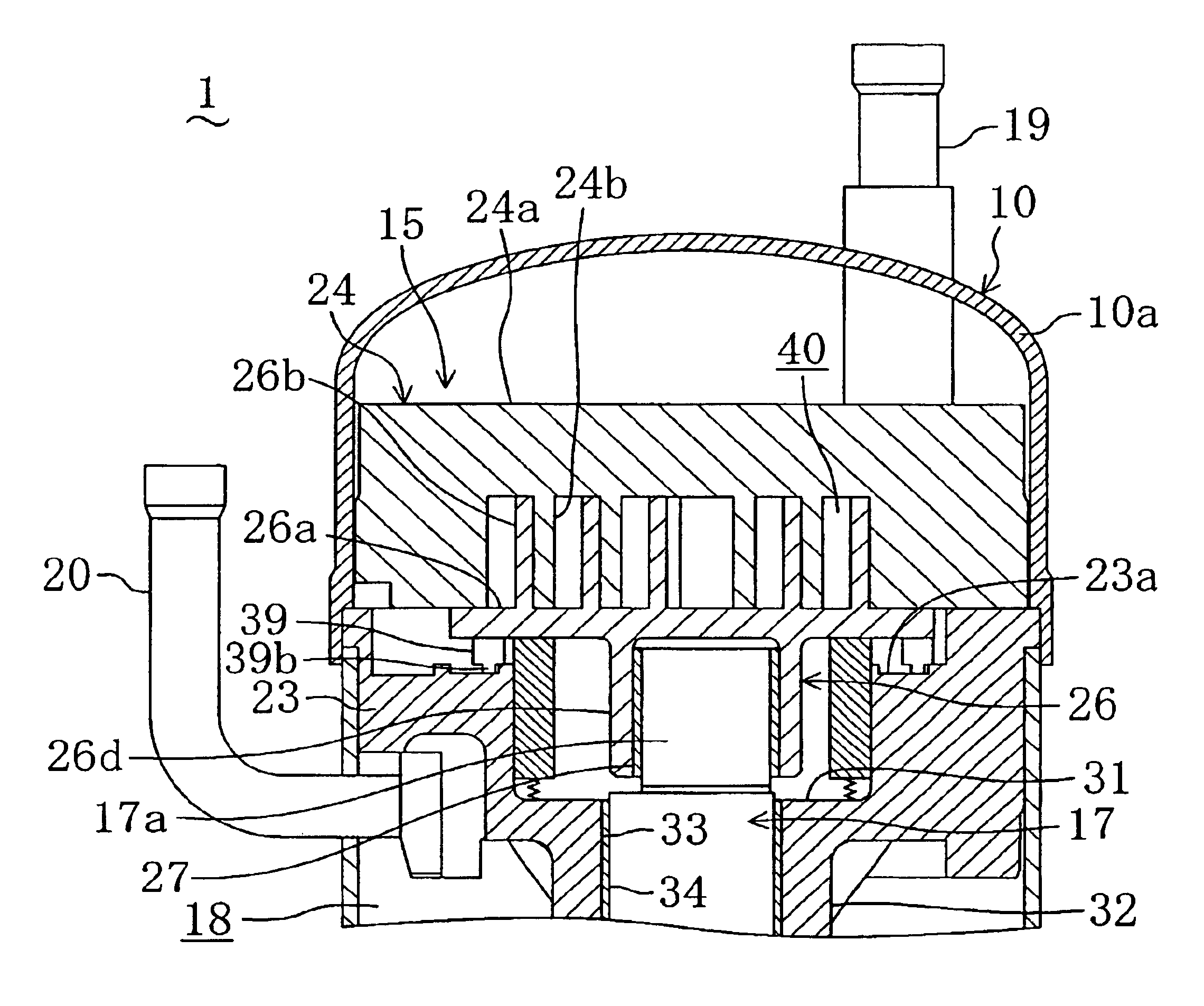
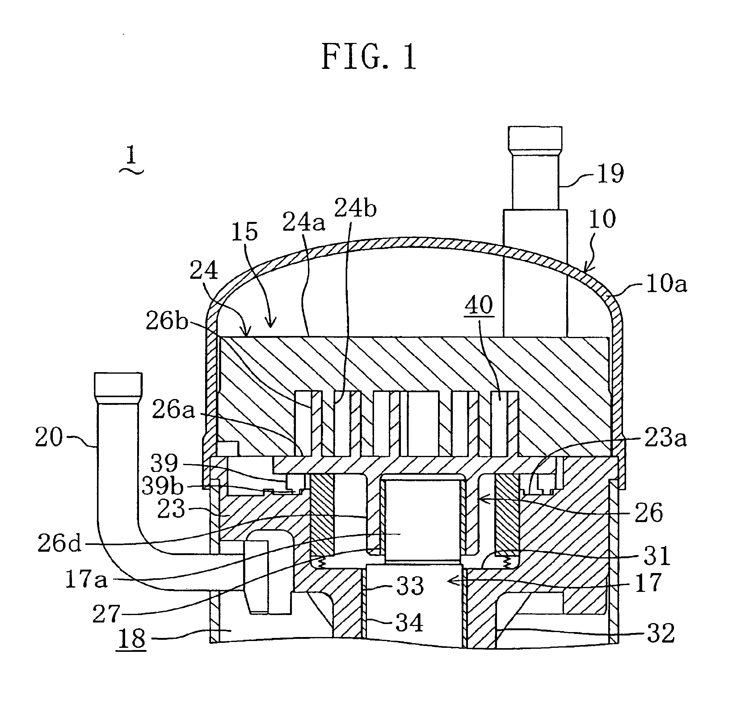
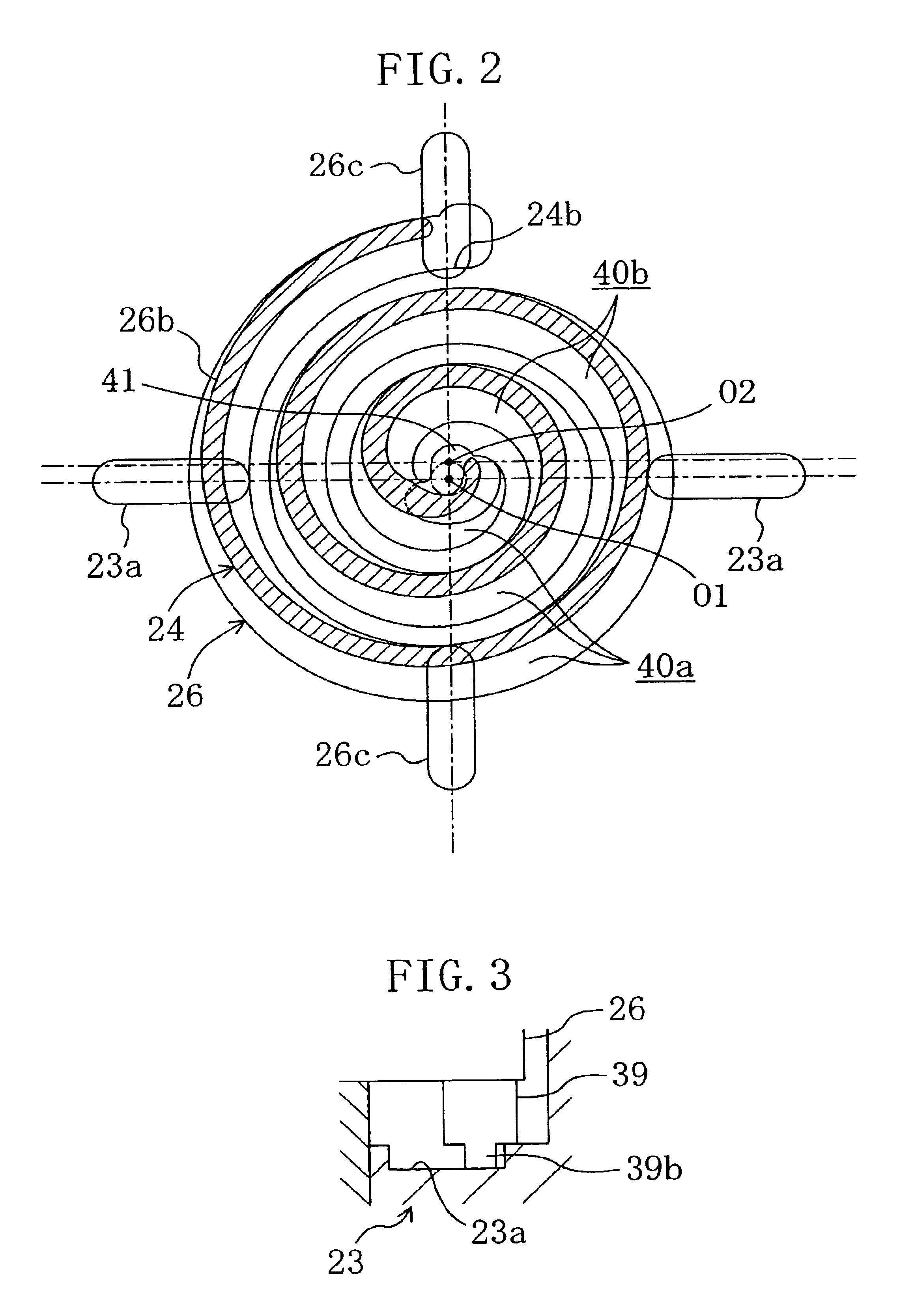
[0041]An embodiment of the present invention will be described in detail with reference to the accompanying drawings. FIG. 1 shows a scroll compressor (1) according to the present embodiment. The scroll compressor (1) is connected to a refrigerating circuit, not shown in any drawing, which performs a vapor-compression type of refrigerating-cycle operation with a refrigerant circulated therein.

[0042]The scroll compressor (1) includes a sealed dome-type casing (10) with a longitudinal-cylinder shape. In the casing (10), a scroll compressing mechanism (15) to compress the refrigerant and a driving motor (not shown in any drawing) disposed below the scroll compressing mechanism (15) are installed. The scroll compressing mechanism (15) and the driving motor are coupled by a drive shaft (17) that is disposed in the casing (10) so as to extend in the vertical direction. Between the scroll compressing mechanism (15) and the driving motor, a high-pressure space (18) filled with a compressed ...


PUM


Abstract

In a scroll compressor, a sliding direction of a Oldham coupling is defined such that an acting direction of an inertia force of the Oldham coupling is substantially opposite to an acting direction of a reaction force by gas compression, and thereby a range of fluctuation of a total torque of a first rotational torque acting on an orbiting scroll by the reaction force of gas compression and a second rotational torque of sliding movement of the Oldham coupling becomes smaller than that of the first rotational torque to suppress a noise and vibration caused by fluctuation of a rotational torque of the orbiting scroll without any limited designing of an involute shape thereof.

Description

TECHNICAL FIELD[0001]The present invention relates to a scroll compressor, and particularly to a technology of suppressing an operating noise and vibration caused by fluctuation of a rotational torque of an orbiting scroll.BACKGROUND ART[0002]Conventionally, a scroll compressor has been used as a compressor to compress a refrigerant in a refrigerating cycle, as disclosed, for example, in Japanese Laid-Open Patent Publication No. 5-312156. The scroll compressor includes a compression mechanism with a fixed scroll and an orbiting scroll that have protruding involute wraps engaged with each other in a casing. The fixed scroll is fixed to the casing by, for example, a fixing member (hereinafter, referred to as a housing) and the orbiting scroll is coupled to an eccentric shaft portion of a drive shaft. Further, the scroll compressor is constituted such that the orbiting scroll just revolves orbitally to the fixed scroll without rotating on its own axis, thereby contracting a compression...

Claims


Application Information

Patent Timeline
Patent Type & Authority Patents(United States)
IPC IPC(8): F01C17/00F01C17/06F04C18/02F04C29/00F04C23/00
CPCF01C17/066F04C29/0021F04C23/008F04C18/0215F04C18/02
Inventor YAMAJI, HIROYUKIKATO, KATSUMIHIGUCHI, MASAHIDE
Owner DAIKIN IND LTD
Why Eureka
Try Eureka