Heat roller and method of fabricating the same

Inactive Publication Date: 2005-09-06
FUJIFILM BUSINESS INNOVATION CORP
View PDF13 Cites 7 Cited by
  • Summary
  • Abstract
  • Description
  • Claims
  • Application Information

AI Technical Summary

Benefits of technology

[0015]In this way, a heat roller having a ring m

Problems solved by technology

However, the halogen lamp is low in thermal efficiency, and moreover, the rubber covering the metallic ring member reduces the thermal efficiency.
In addition, it takes several ten seconds to several minutes to

Method used


Image

  • Heat roller and method of fabricating the same
  • Heat roller and method of fabricating the same
  • Heat roller and method of fabricating the same

Examples


Embodiment Construction

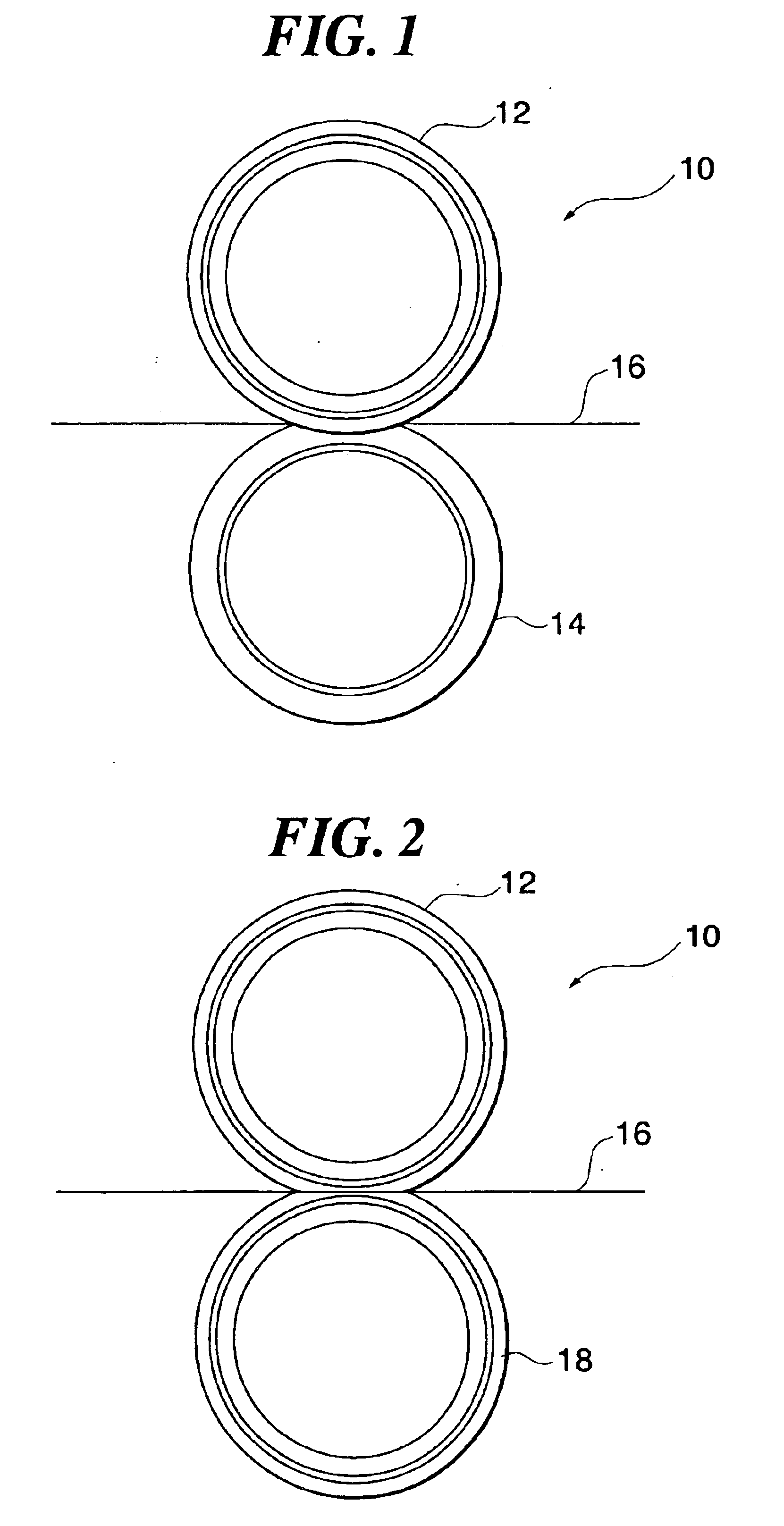
[0033]FIG. 1 is a side view showing a fixing device including a heat roller according to one embodiment of the present invention. A fixing device 10 includes a heat roller 12 and a pressure roller 14 that is pressed into contact with the heat roller 12 and is covered with rubber. A sheet 16 is transported between the heat roller 12 and the pressure roller 14, whereupon toner carried by the sheet 16 is melted by heat generated by the heat roller 12 and is pressurized between the heat roller 12 and the pressure roller 14, to thereby be fixed.

[0034]FIG. 2 is a side view showing a fixing device including a heat roller according to another embodiment of the present invention. A fixing device 10 includes a heat roller 12 and a heat roller 18, serving as a pressure roller, that is pressed into contact with the heat roller 12. The heat roller 18 has a configuration similar to that of the heat roller 12. In this case, a toner carried by the sheet 16 is melted by heat generated by the heat ro...


PUM

PropertyMeasurementUnit
Electrical resistanceaaaaaaaaaa
Shapeaaaaaaaaaa

Abstract

A heat roller has a cylindrical sheet-like heating element, an inner tube and an outer tube. The sheet-like heating element has a resistance member embedded into an insulating member. The outer tube has a non-linear shape seen in an axial direction. The heat roller is fabricated by supplying pressurized fluid to the inner tube for expanding the inner tube, sheet-like heating element and outer tube toward a die. The die has a non-linear inner shape seen in the axial direction. Therefore, the outer tube of the fabricated heat roller has a non-linear shape. Further, an edge section of the inner tube can simultaneously be formed into a desired shape.

Description

CROSS-REFERENCE TO RELATED APPLICATIONS[0001]This application is a continuation of PCT / JP02 / 05444, filed on Jun. 3, 2002, the contents being incorporated therein by reference.TECHNICAL FIELD[0002]The present invention relates to a heat roller and a method of fabricating the same. In particular, the present invention relates to, for example, a heat roller suitable for use in a fixing device used in an electrophotographic device.BACKGROUND ART[0003]An electrophotographic device (copying machine, facsimile device, printer and the like) has an image forming device and a fixing device for fixing an image formed and transferred onto a sheet by the image forming device. The fixing device includes a heat roller.[0004]A heat roller is formed of a metallic ring member, rubber covering the metallic ring member and a halogen lamp arranged inside the metallic ring member. However, the halogen lamp is low in thermal efficiency, and moreover, the rubber covering the metallic ring member reduces th...

Claims


Application Information

Patent Timeline
IPC IPC(8): G03G15/20G03G13/20H05B3/00
CPCG03G13/20G03G15/2053G03G15/2064H05B3/0095G03G15/2057G03G15/206Y10T29/49083G03G2215/2061
Inventor SANPEI, KOICHIMORI, MITSUHIROKIMURA, MASATOSHIKONISHI, MASAO
Owner FUJIFILM BUSINESS INNOVATION CORP
Why Eureka
Try Eureka