
Dynamic tessellation of a base mesh

a dynamic tessellation and mesh technology, applied in the field of rendering graphical images, can solve the problems of more processor resources, longer time requirements, and increased processing resources, and achieve the effect of preventing cracking and efficient utilization of processing resources

Inactive Publication Date: 2005-09-06
MATROX
View PDF7 Cites 131 Cited by
  • Summary
  • Abstract
  • Description
  • Claims
  • Application Information

AI Technical Summary

Benefits of technology

[0016]Accordingly, an object of the present invention is to provide a method of tessellating a primitive which permits efficient utilization of processing resources, prevents cracking, and ensures topological and geometric continuity.

Problems solved by technology

However, the amount of processing resources required to render an image is directly related to the number of polygons within the mesh.
As a result, rendering a highly detailed image (consisting of a large number of polygons) of an object requires more processor resources, and thus typically takes longer, than rendering an image of the same object with less detail.
However, since smooth animation requires that an image be refreshed at a rate of at least 30 frames per second, a compromise between animation performance and rendering detail must normally be found.
As may be appreciated, uniform tessellation tends to yield a highly inefficient utilization of processor resources.
Another problem with uniform tessellation is that primitives facing away from the camera (which are inherently invisible) will be tessellated at the same rate as the visible primitives.
This incurs a further waste of processing resources.
A similar problem exists for primitives that are oriented at an angle near the “line of sight” from the camera position.
However, non-uniform tessellation suffers the problem that “cracks” can form along a shared edge between adjacent primitives with differing tessellation rates.
In particular, a crack can occur at a “T-junction”, which is formed when a vertex lying on a shared edge between a pair of primitives is connected to a polygon defined in only one of the involved primitives.
In either scenario, rounding errors and misalignment between the local coordinate systems of the involved primitives can result in differences between the coordinates of vertices (calculated relative to each primitive) that should overlay one another, which causes a gap (or crack) to open between the two primitives.
A crack in object A can result in object B being at least partially visible through object A, which is clearly undesirable.
However, this solution consumes substantial processing resources, and thus at least partially negates the benefits of adopting a non-uniform tessellation regime.
The sudden appearance and disappearance of features is referred to as “popping”, and is clearly undesirable.
However, such popping is commonly encountered in conventional systems, because changes in the tessellation rate unavoidably involve changing the tessellation scheme, as at least some large polygons are replaced by two or more smaller polygons.

Method used


Image

  • Dynamic tessellation of a base mesh
  • Dynamic tessellation of a base mesh
  • Dynamic tessellation of a base mesh

Examples


Embodiment Construction

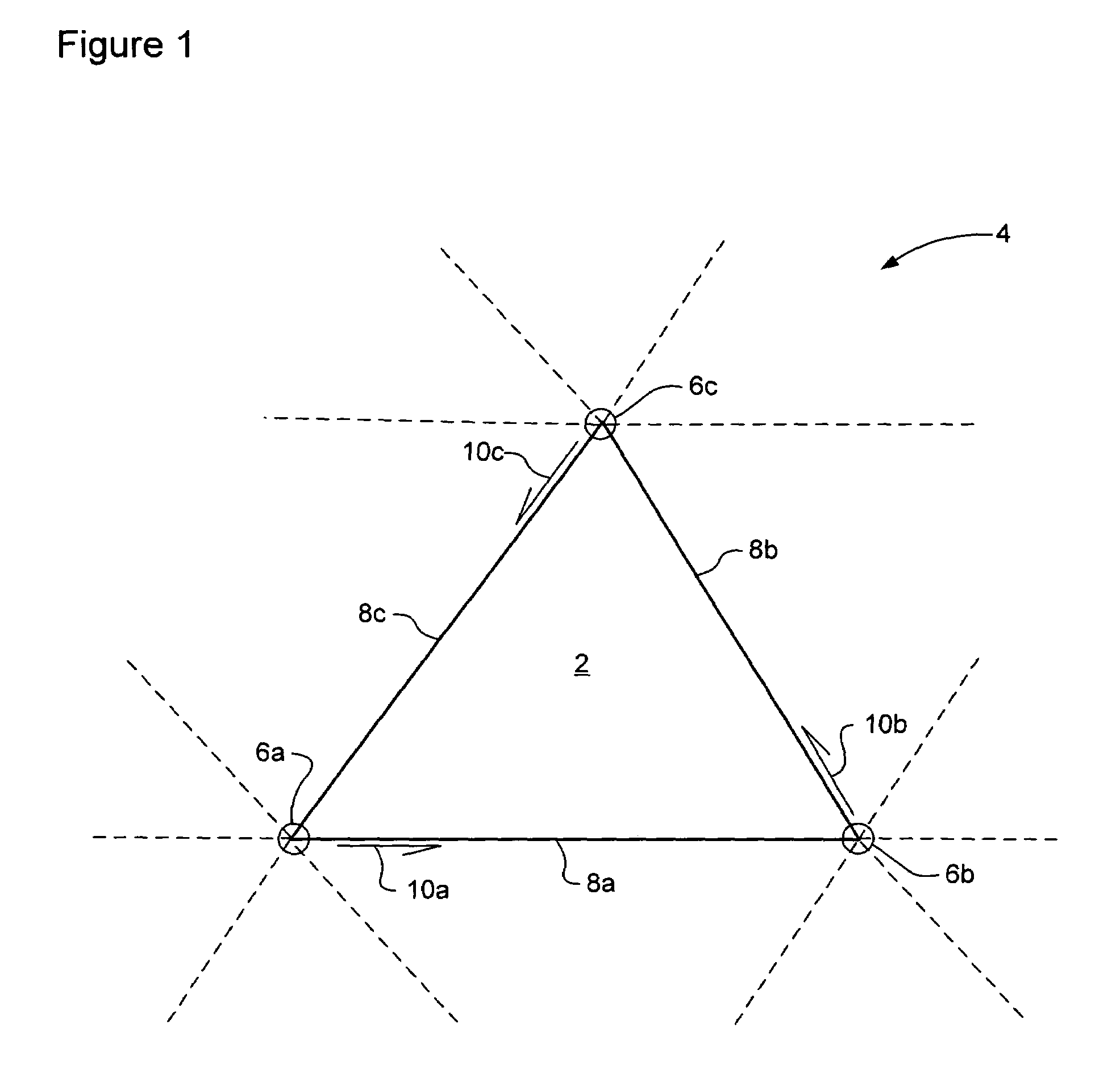
[0027]The present invention provides a method of tessellating a base mesh consisting of a plurality of base vertices interconnected by base mesh edges defining polygonal primitives of the base mesh. FIG. 1 schematically illustrates a base mesh primitive 2 within an exemplary base mesh 4. As shown in FIG. 1, the primitive 2 is defined by a respective set of base mesh vertices 6 that are interconnected by base mesh edges 8.

[0028]In general, the base mesh 4 may be composed of primitives 2 of any arbitrary shape. However, for computational efficiency and versatility, triangular primitives are preferred. In this case, the base mesh 4 can be provided as an arbitrary mesh of triangular primitives 2, defined by a base vertex array and connectivity information in the form of a primitive list. In order to prevent cracking, T-junctions within the base mesh 4 should be avoided. In addition, improved image rendering may be obtained by defining the base vertex array and primitive list such that t...


PUM


Abstract

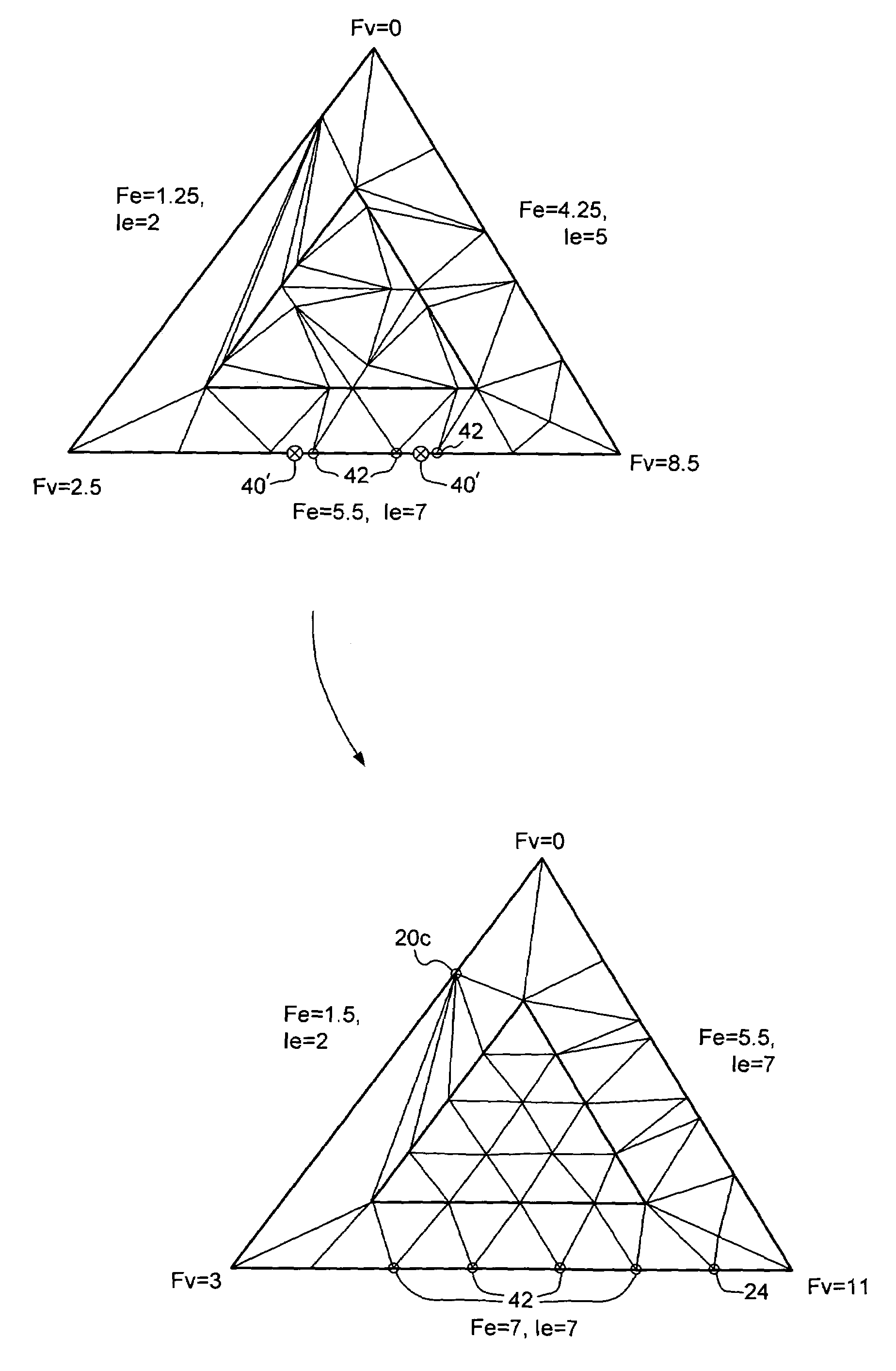
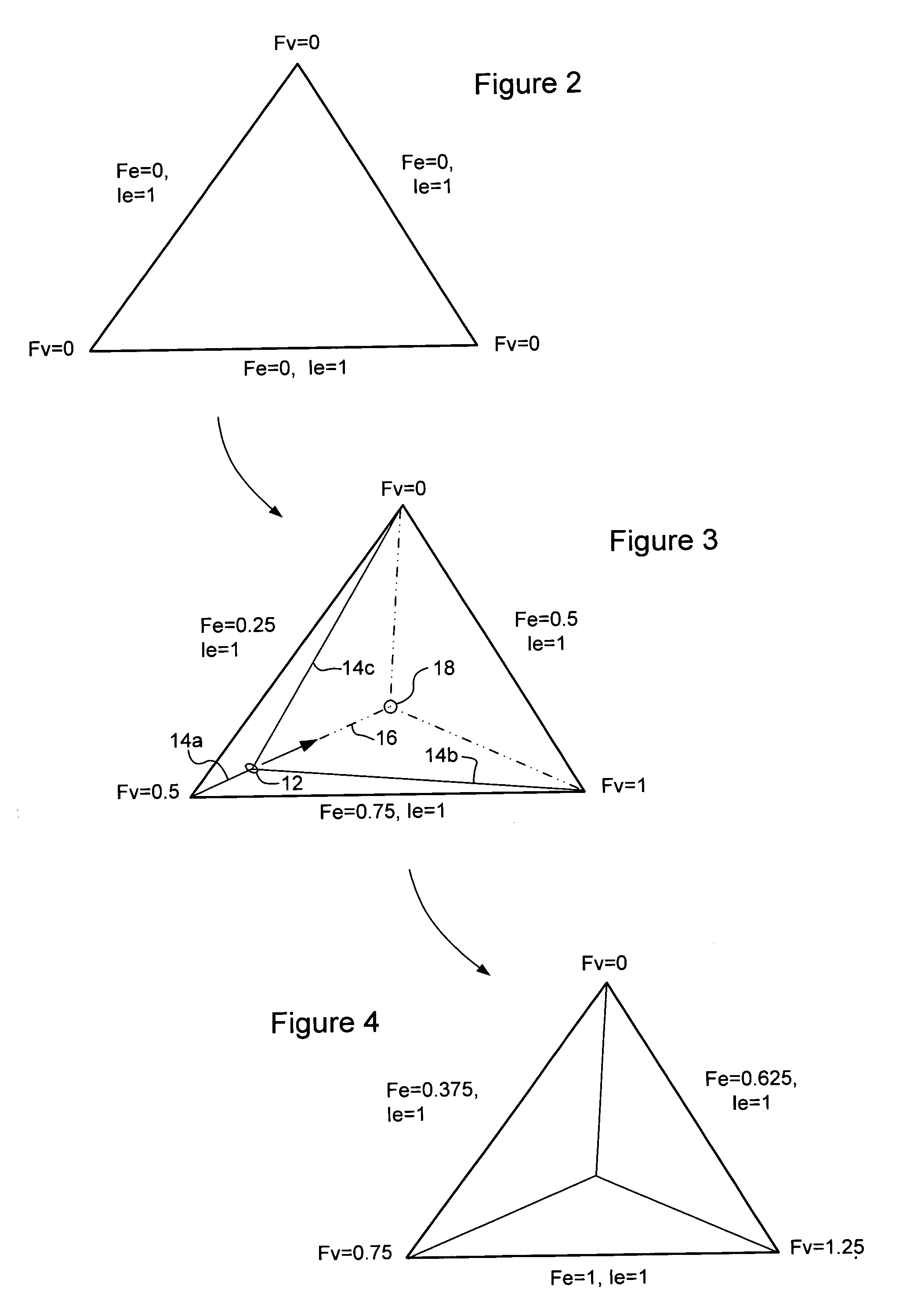
A primitive of a base mesh having at least three base vertices is dynamically tessellated to enable smooth changes in detail of an image rendered on a screen. A respective floating point vertex tessellation value (Fv) is assigned to each base vertex of the base mesh, based on a desired level of detail in the rendered image. For each edge of the primitive: a respective floating point edge tessellation rate (Fe) of the edge is calculated using the respective vertex tessellation values (Fv) of the base vertices terminating the edge. A position of at least one child vertex of the primitive is then calculated using the respective calculated edge tessellation rate (Fe). By this means, child vertices of the primitive can be generated coincident with a parent vertex, and smoothly migrate in response to changing vertex tessellation values of the base vertices of the primitive.

Description

CROSS-REFERENCE TO RELATED APPLICATIONS[0001]This is the first application filed for the present invention.MICROFICHE APPENDIX[0002]Not Applicable.TECHNICAL FIELD[0003]The present invention relates to the rendering of graphical images on a screen, and in particular to dynamic tessellation of a base mesh enabling smooth changes in the level of detail of an image rendered on a screen.BACKGROUND OF THE INVENTION[0004]As is well known in the art, one of the techniques for rendering an image of an object on a screen (such as, for example, a computer monitor) involves defining a piece-wise approximation of surface contours of the object using a “mesh” composed of a number of (nominally planar) polygons. Typically, all of the polygons within the mesh will be geometrically similar (rectangular or triangular, for example) but their size and shape will vary. Because the vertices of each polygon can be explicitly defined, the mesh can be readily mapped to appropriate pixel coordinates of the s...

Claims


Application Information

Patent Timeline
IPC IPC(8): G06T17/20
CPCG06T17/20G06T17/205
Inventor SAVINE, DMITRIBEAUDOIN, PHILIPPE JEANCARDENAS, JUAN MIGUEL GUARDADOOSTIGUY, JEAN-JACQUES
Owner MATROX
Learn More