Cost-efficient clothes dryer

Active Publication Date: 2005-09-13
ZIELEWICZ ROBERT +4
View PDF14 Cites 55 Cited by
  • Summary
  • Abstract
  • Description
  • Claims
  • Application Information

AI Technical Summary

Benefits of technology

[0011]It is another object of the invention to provide a clothes dryer that is cost-efficient.
[0012]It is another object of the invention to provide a clothes dryer that eliminates any chance of fire through

Problems solved by technology

In certain areas of the country where energy costs are high, running an electrically operated clothes dryer can be very expensive.
Gas operation is not always a choice in some areas,

Method used


Image

  • Cost-efficient clothes dryer
  • Cost-efficient clothes dryer
  • Cost-efficient clothes dryer

Examples


Embodiment Construction

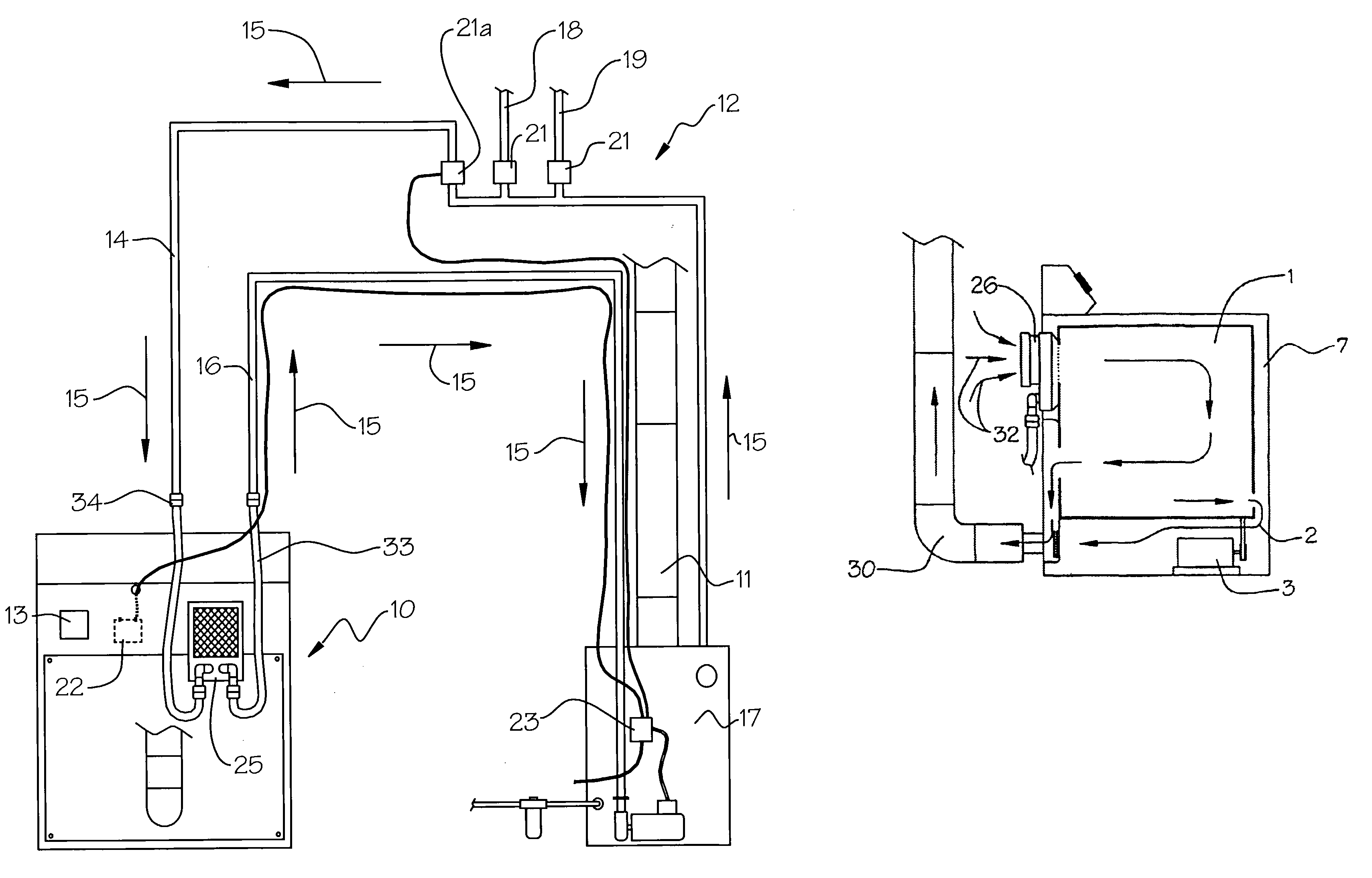
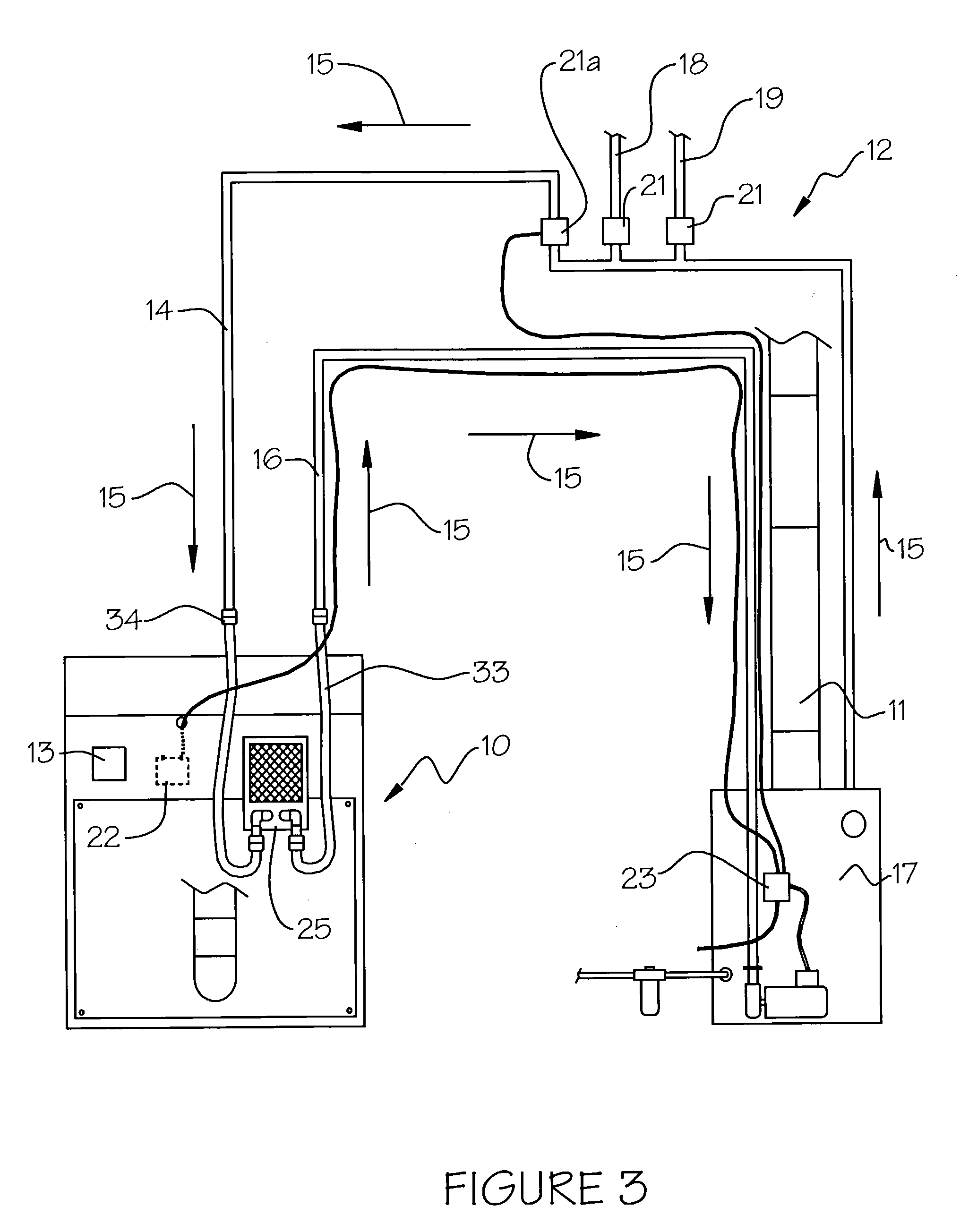
[0023]Generally speaking, a clothes dryer that is operatively attached to a home heating system is illustrated. The clothes dryer is operatively attached to the home heating boiler and receives heated fluid when the dryer is turned on. The dryer comprises a radiator that receives the heated fluid from the fluid flow system. The fluid-filled radiator radiates heat into a clothes-drying chamber, which forms part of a motor-driven rotating drum. The rotating drum tumbles the clothes as heat is projected into the drying chamber, thus driving the moisture from the clothes.

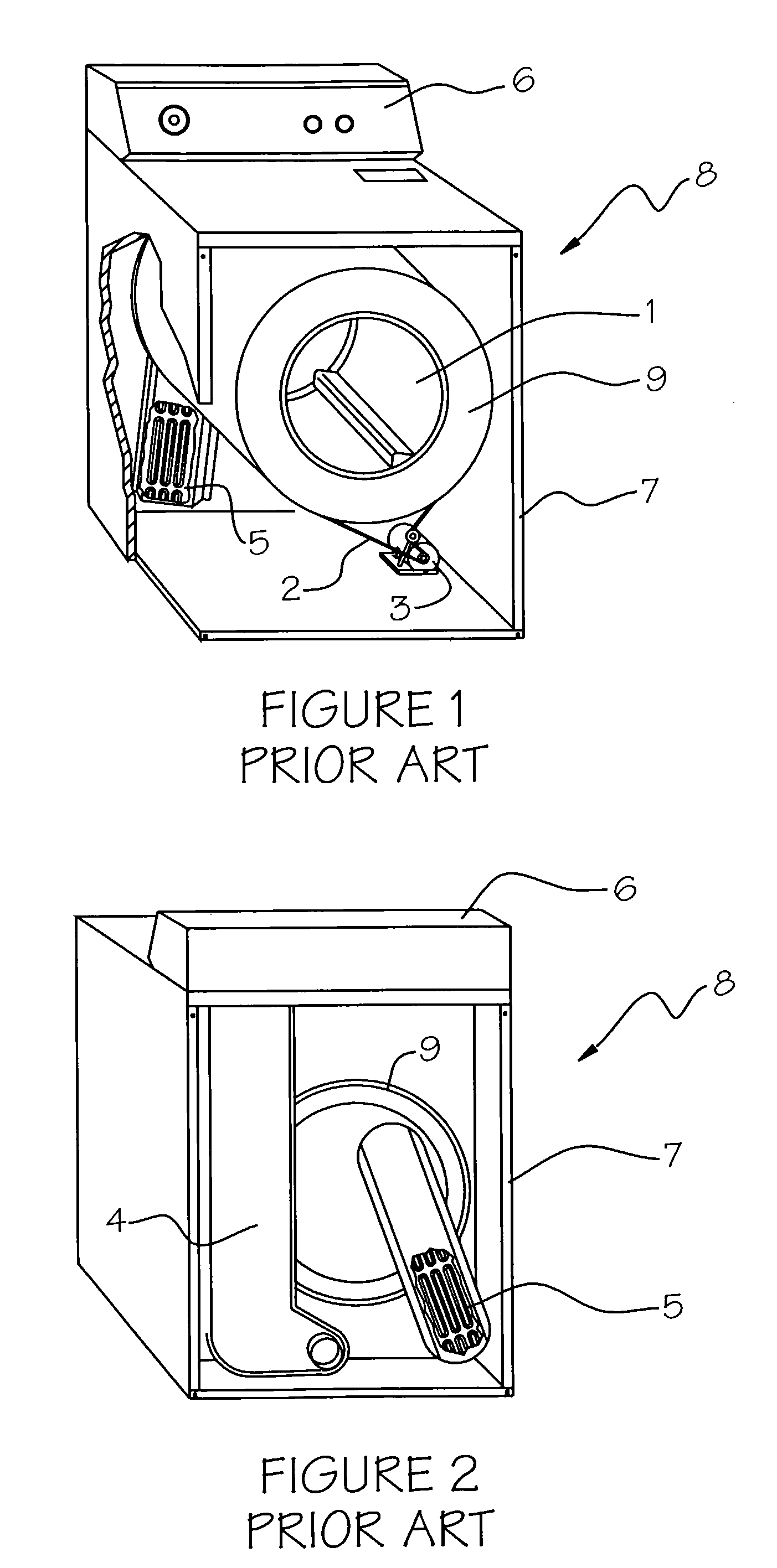
[0024]Now referring to FIGS. 1 and 2, a prior art clothes dryer 8 is illustrated by front and rear perspective cutaway views. The clothes dryer 8 comprises a housing 7 containing a rotating drum 9 having an inner drying chamber 1, into which wet clothes (not shown) are deposited. The clothes dryer 8 has a control panel 6 for selecting the drying cycle and fabric type. The drum 9 obtains its heat from a set of electrical...


PUM


Abstract

A clothes dryer that is operatively attached to a heating system is illustrated. The clothes dryer receives heated fluid when the dryer is turned on. The dryer has a radiator that receives the heated fluid from the circulating fluid flow system. The fluid-filled radiator radiates heat into a clothes-drying chamber, which forms part of a motor-driven, rotating drum. The rotating drum tumbles the clothes as heat is projected into the drying chamber, thus driving the moisture from the clothes.

Description

FIELD OF THE INVENTION[0001]The invention pertains to clothes dryers and, more particularly, to a cost-efficient clothes dryer that is connected to the heating system of a house and operates as a heating zone peripheral.BACKGROUND OF THE INVENTION[0002]In certain areas of the country where energy costs are high, running an electrically operated clothes dryer can be very expensive. Gas operation is not always a choice in some areas, leaving the homeowner with few options other than running a costly electric clothes dryer. Even where gas is available, operating a gas-fired clothes dryer can still be inefficient. A large portion of the heat transferred to the drying chamber is vented to the atmosphere without heating the clothes. Other advantages include no chance of fire caused by gas or electric heat sources, and elimination of overheating and scorching fabrics since temperatures of water / heat radiation are lower than gas or electric heat sources.[0003]A home heating system is often ...

Claims


Application Information

Patent Timeline
IPC IPC(8): F26B11/02F26B11/00D06F34/18
CPCD06F58/20D06F58/26D06F34/18D06F2103/08
Inventor ZIELEWICZ, ROBERTZIELEWICZ, KARENZIELEWICZ, SARAHZIELEWICZ, MATTHEWZIELEWICZ, EMILY
Owner ZIELEWICZ ROBERT
Why Eureka
Try Eureka