Article of footwear with a replaceable ground-engaging member and method of attaching the ground-engaging member

a technology of replacing ground-engaging members and footwear, which is applied in the direction of fastenings, uppers, bootlegs, etc., can solve the problems of time-consuming and laborious, conventionally difficult to recognize when the ground-engaging member has been adequately tightened, and it is difficult or even impossible to subsequently disengage the ground-engaging member from the shoe when desired, so as to avoid the time-consuming conventional process and achieve quick and assured adjustment

Inactive Publication Date: 2005-09-13
NIKE INC
View PDF33 Cites 55 Cited by
  • Summary
  • Abstract
  • Description
  • Claims
  • Application Information

AI Technical Summary

Benefits of technology

[0011]A ground-engaging member according to the present invention is preferably engaged with the sole in a non-rotational manner, such as by simply applying a substantially non-rotational linear force to engage the ground-engaging member with the sole. Such a non-rotational action can be ensured, for example, by providing a rotation preventing mechanism. For example, a rib, spline, ridge, etc. may be provided on one of the ground-engaging member and a corresponding portion of the sole, and a slot, groove, etc. is provided in the other of the ground-engaging member and the corresponding portion of the sole. The rib and slot cooperate in the process of engaging the ground-engaging member with the sole so the ground-engaging member can only be linearly moved into engagement with the sole, with substantially no relative rotation therebetween. Once the ground-engaging member is engaged with the sole, the rotation prevention mechanism additionally prevents subsequent relative rotation between the ground-engaging member and the sole.
[0014]A ground-engaging member according to the present invention may include a selectively removable tip that is engaged with a portion of the sole in accordance with the foregoing description. Furthermore, each portion of the sole may be engageable with several such tips, at least some of which have different heights, such that a given tip may be replaced with another tip having a different height. In this manner, the characteristics (especially, but not necessarily only, ground-engaging characteristics) of the article of footwear may be adjusted quickly and assuredly in accordance with changing playing conditions by avoiding the time-consuming conventional process of using a screw tool to engage and disengage conventional ground-engaging members, while additionally permitting sure engagement of a ground-engaging member because of the detectible feedback provided in accordance with the present invention.

Problems solved by technology

This is generally time consuming and labor intensive, and is also problematic if a user decides to change ground-engaging members in a hurried manner, such as during the course of a game, for example.
However, it is conventionally difficult to recognize when the ground-engaging member has been adequately tightened.
This can damage the screw threads on the shoe and / or on the ground-engaging member, making it difficult or even impossible to subsequently disengage the ground-engaging member from the shoe when desired.
On the other hand, the ground-engaging member may be inadvertently under-torqued (for example, to avoid damage caused by over-torquing).
When this occurs, the ground-engaging member may not function as a stable traction device and / or may become loose and be susceptible to falling off of the shoe.
While some conventional ground-engaging members are not threadedly engaged with a shoe, they still suffer from structural and / or functional problems.
This can be a problem when, for example, the ground-engaging member is axially asymmetrical in shape (for example, conical or frusto-conical) because free edges of an axially asymmetrical ground-engaging member can become exposed, caught on objects and such, and be torn away.
Furthermore, relative movement between a ground-engaging member and a sole generally destabilizes the engagement between the ground-engaging member and the sole, compared to holding them fixed relative to one another.
Thus, the receiving portion may possibly be sheared off the sole or may otherwise become dislodged.

Method used


Image

  • Article of footwear with a replaceable ground-engaging member and method of attaching the ground-engaging member
  • Article of footwear with a replaceable ground-engaging member and method of attaching the ground-engaging member
  • Article of footwear with a replaceable ground-engaging member and method of attaching the ground-engaging member

Examples


Embodiment Construction

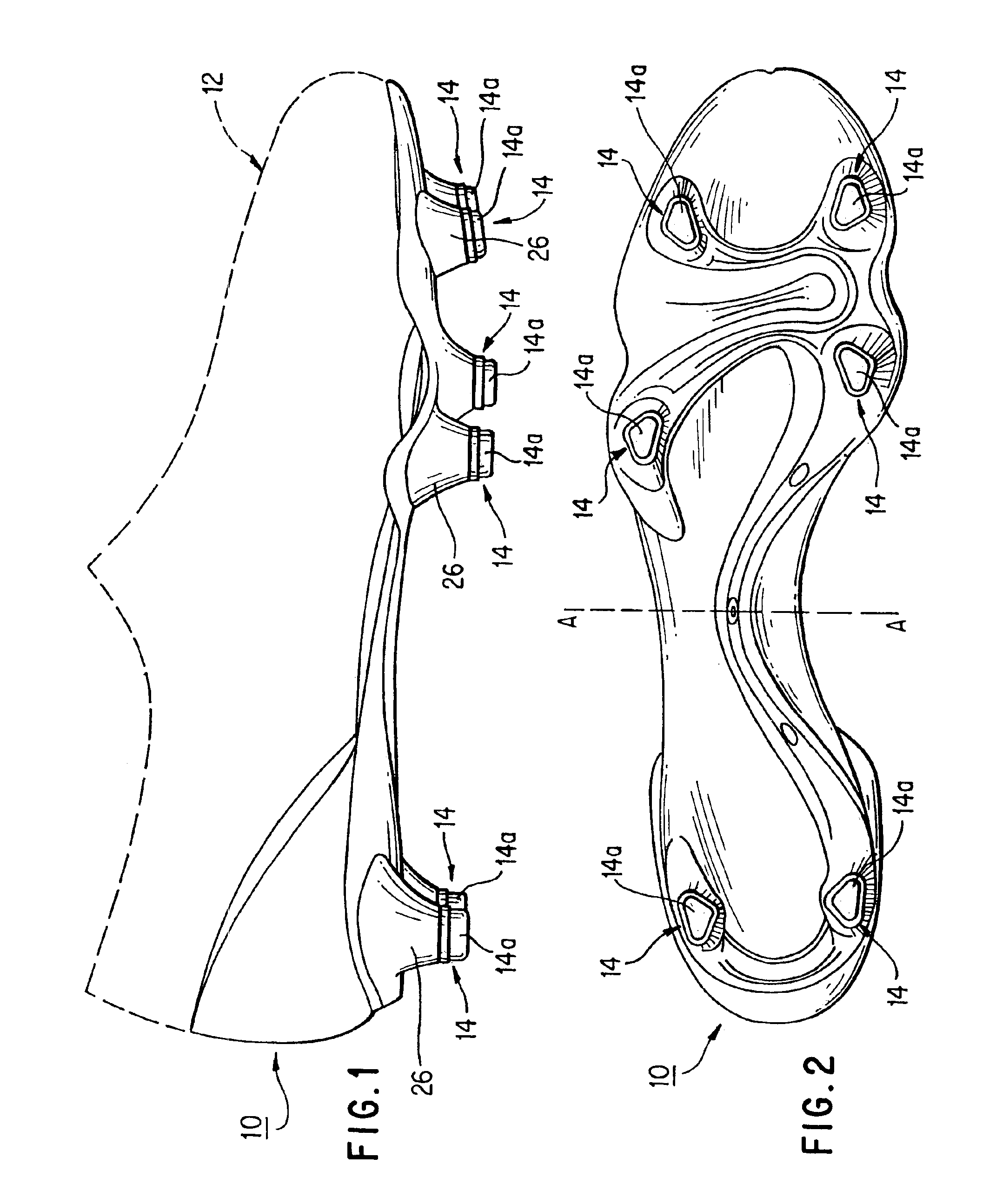
[0028]FIG. 1 is a lateral (i.e., from the laterally outer side) elevational view of a footplate 10 of an article of footwear, such as a shoe (particularly, but not necessarily only, an athletic shoe). A right shoe happens to be illustrated by way of example, but this should not be taken as limiting the present invention. In order to assist in the understanding of the subject matter illustrated in the figures, a generic profile of a shoe upper 12 is indicated in phantom in FIG. 1.

[0029]For the purposes of the description herein, the article of footwear has a “sole” which includes footplate 10. However, other parts that may be included in a sole, such as a midsole, etc. have been omitted from the drawings for clarity.

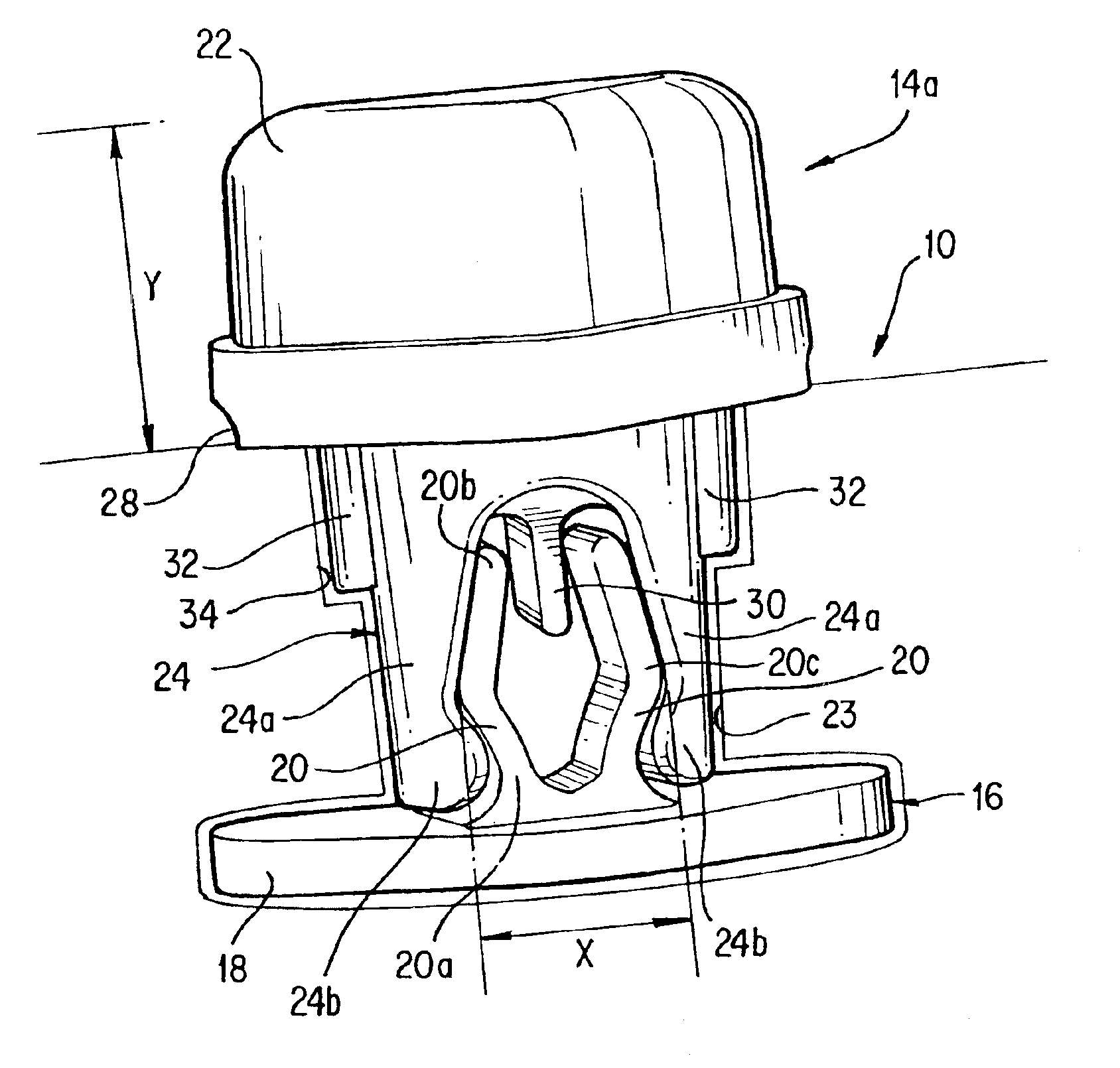
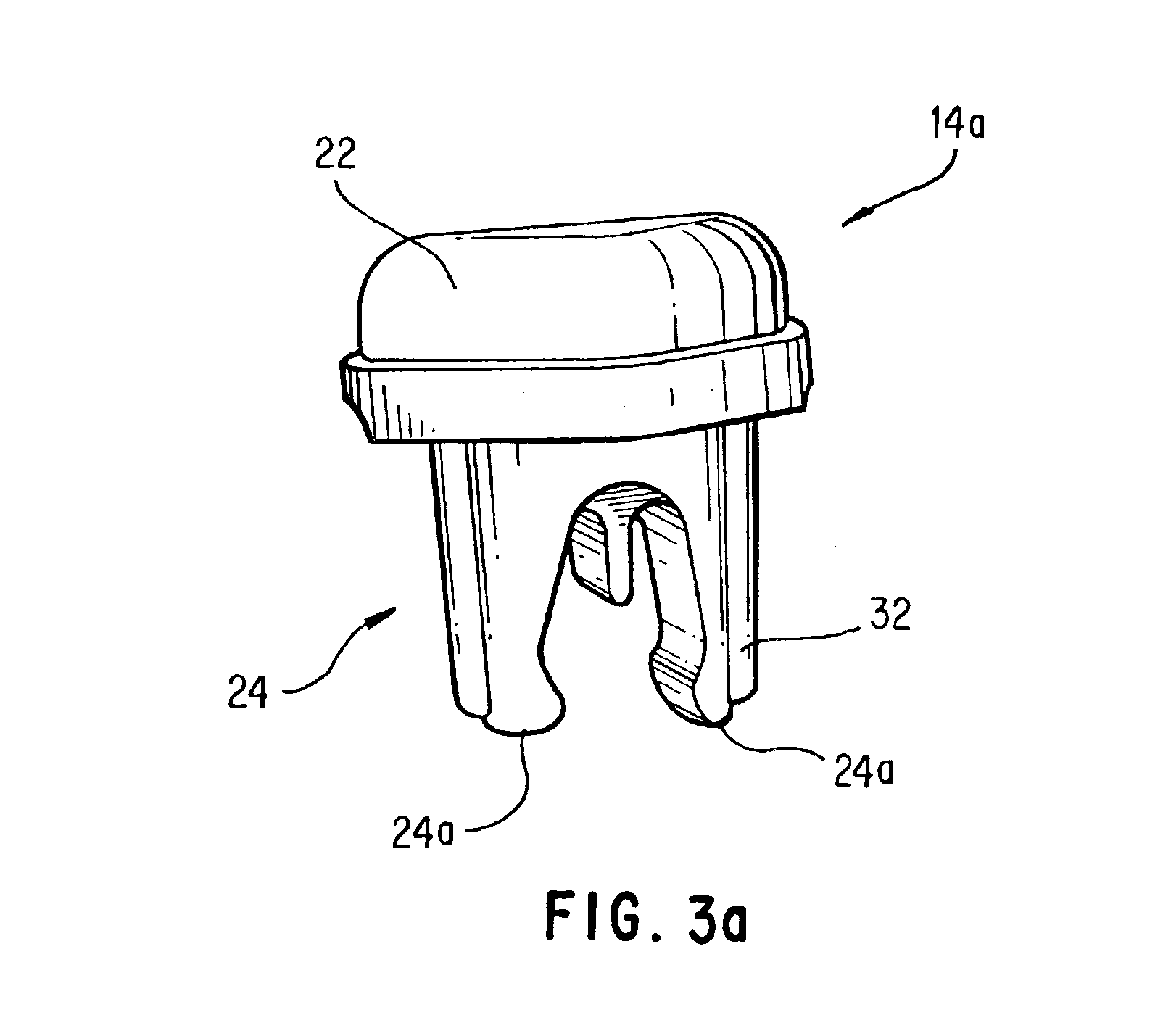
[0030]Footplate 10 includes at least one ground-engaging member 14 extending from footplate 10. Commonly, footplate 10 includes a plurality of ground-engaging members 14 distributed over the surface of footplate 10. FIG. 2 illustrates one example of how ground-engaging me...


PUM


Abstract

An article of footwear provided with snap-fit replaceable ground-engaging members, particularly snap-fit tips, and a kit and method for altering ground-engaging characteristics of an article of footwear such as an athletic shoe. An article of footwear according to the present invention includes a sole (and / or a footplate) having at least one ground-engaging member in snap-fit engagement therewith. In particular, the ground-engaging member is engageable under the application of a non-rotational force (especially a manual force). According to one aspect of the present invention, a clearly discernible feedback (especially an audible feedback, such as a click or a snapping sound) is provided to clearly indicate engagement between the ground-engaging member and the sole.

Description

CROSS-REFERENCE TO RELATED APPLICATION[0001]This application is a Continuation of U.S. patent application Ser. No. 09 / 988,737 filed Nov. 20, 2001, now U.S. Pat. No. 6,722,061 which is hereby incorporated by reference.FIELD OF THE INVENTION[0002]The present invention relates to an article of footwear having one or more ground-engaging members, especially an athletic shoe having one or more selectively alterable ground-engaging members (such as spikes, cleats, etc.).BACKGROUND OF THE INVENTION[0003]It is generally known to provide one or more protruding ground-engaging members on the sole of a shoe, especially on the sole of an athletic shoe for activities such as golf, soccer, track, baseball, and “American-style” football. Such ground-engaging members are variously known in the art as cleats, spikes, studs, leaves, blades, triangles, nubs, etc., and generally serve to increase traction between the shoe and the ground surface.[0004]Furthermore, it is conventionally known to use parti...

Claims


Application Information

Patent Timeline
Patent Type & Authority Patents(United States)
IPC IPC(8): A43C15/00A43C15/16
CPCA43C15/161A43C15/162A43D100/14
Inventor AUGER, PERRYLINDNER, TROYHUDSON, PETER A.
Owner NIKE INC
Why Eureka
Try Eureka