
Stiffening assembly for stiffening the lower frame assembly of a blanking tool

a technology of blanking tool and frame assembly, which is applied in the direction of manufacturing tools, application, and connection of rods, can solve the problems of cumbersome and time-consuming disassembly of inner grids from outer frames, and achieve the effect of reducing flexing of frame assemblies and being easy to attach and remov

Inactive Publication Date: 2005-09-13
BLANKING SYST
View PDF8 Cites 30 Cited by
  • Summary
  • Abstract
  • Description
  • Claims
  • Application Information

AI Technical Summary

Benefits of technology

[0007]Therefore, it is a primary object and feature of the present invention to provide an improved stiffening assembly for stiffening a frame assembly for a lower blanking tool of a carton die cutting machine to reduce flexing of the frame assembly during a blanking operation.
[0008]It is a further object and feature of the present invention to provide a stiffening assembly for stiffening a frame assembly for a lower blanking tool that may be easily attached and removed from the frame assembly.
[0009]It is a still further object and feature of the invention to provide a stiffening assembly for stiffening a frame assembly for a lower blanking tool which is compatible with standard blanking operation machinery and which is relatively inexpensive.
[0110]A sheet of paper material 410 is placed on upper surface 408 of grid element 400. The lower surface 410a of the sheet engages the flyers 456 so as to urge the flyers into corresponding recesses 450 in upper surfaces 426 of supporting elements 424, FIG. 31. Thereafter, an upper tool is used in combination with lower frame assembly 10 to knock the carton blanks from the sheet of paper material 410 through openings 420 in grid element 400 while the scrap material is retained on grid element 400. Once the upper tool is withdrawn from lower frame assembly 10, flyers 456 raise the scrap portion of the sheet of paper material 410 off upper surface 408 of grid element 400 so as to prevent the scrap material from getting caught on grid element 400 when being removed from lower frame assembly 10.

Problems solved by technology

Thus, the disassembly of the inner grid from the outer frame and the grid element from the inner grid oftentimes becomes very cumbersome and time consuming.

Method used


Image

  • Stiffening assembly for stiffening the lower frame assembly of a blanking tool
  • Stiffening assembly for stiffening the lower frame assembly of a blanking tool
  • Stiffening assembly for stiffening the lower frame assembly of a blanking tool

Examples


Embodiment Construction

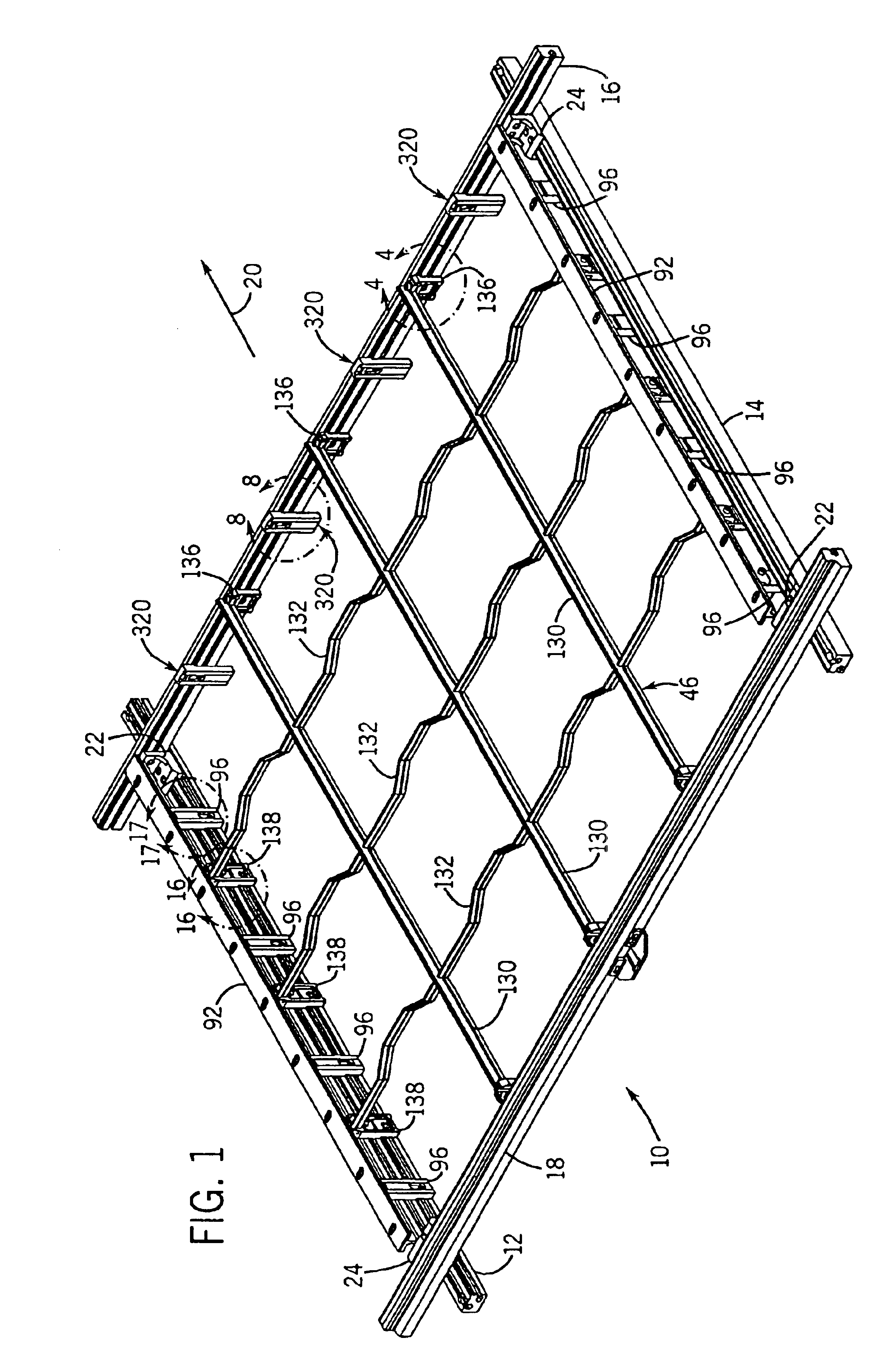
[0054]Referring to FIG. 1, a lower frame assembly for a blanking tool of a carton die cutting machine is generally designated by the numeral 10. As is known, a die cutting machine converts or processes a sheet of paper material into a carton blank. These machines are well known in the art and are used to cut one or several blanks into each sheet of paper material which, after folding and gluing, may be formed into cartons or boxes. As is conventional, the sheets of paper material move in a substantially horizontal plane within the machine and are carried through various sequences of printing, cutting, embossing, creasing, waste stripping and / or blanking stations.

[0055]The die cutting machine usually is formed by a series of stations with tile first station being a starting position or input station in which the sheets, which may be preprinted if desired, are taken one by one from the top of a stack to a feed table where they are placed in position against frontal and side guides. Th...


PUM

PropertyMeasurementUnit
Angleaaaaaaaaaa
Angleaaaaaaaaaa
Angleaaaaaaaaaa

Abstract

A stiffening assembly is provided for stiffening an outer frame for a lower blanking tool of a carton die cutting machine to discourage the flexing thereof. The stiffening assembly includes an elongated rod and a clamping piece defining a vertically extending inner face, an opposite vertically extending outer face, and a bore extending between the inner face and the outer face along an axis at an acute angle to the outer face. A jaw element is operatively connected to the clamp piece so as to define a clamp cavity therebetween. The jaw element is movable between a clamping position for retaining a portion of the elongated rod in the clamp cavity and a release position.

Description

CROSS-REFERENCE TO RELATED APPLICATIONS[0001]This case is a continuation-in-part of Ser. No. 10 / 164,478, filed Jun. 6, 2002, now U.S. Pat. No. 6,708,858, and entitled “Clamp Pieces For Lower Frame Assembly of Blanking Tool;” and a continuation-in-part of Ser. No. 10 / 197,188, filed Jul. 17, 2002, now U.S. Pat. No. 6,712,254, and entitled “Stiffening Rail Support;” and a continuation-in-part of Ser. No.: 10 / 197,176, filed Jul. 17, 2002, now U.S. Pat. No. 6,715,953, and entitled “Panel Connection Device;” and a continuation-in-part of Ser. No. 10 / 197,190, filed Jul. 17, 2002, now U.S. Pat. No. 6,796,474, and entitled “Jogger For Lower Frame Assembly Of Blanking Tool;” and a continuation-in part of Ser. No.: 10 / 288,731, filed Nov. 6, 2002 and entitled “Connection Device For Interconnecting A Grid Element To Lower Frame Of A Blanking Tool.FIELD OF THE INVENTION[0002]This invention relates generally to die cutting machines for making carton blanks, and in particular, to a stiffening assem...

Claims


Application Information

Patent Timeline
IPC IPC(8): B26D7/18B26D7/26
CPCB26D7/1818B26D7/2614B26D2007/1881B26D2007/189Y10T403/68Y10T403/7123Y10T403/73Y10T403/7117Y10T403/7111Y10T225/379Y10T83/9423F16B2200/67
Inventor OETLINGER, FRANK E.
Owner BLANKING SYST
Features
  • Generate Ideas
  • Intellectual Property
  • Life Sciences
  • Materials
  • Tech Scout
  • Unparalleled Data Quality
  • Higher Quality Content
  • 60% Fewer Hallucinations
Learn More