
Lifter

a lifter and lifting device technology, applied in the field of lifters, can solve the problems of unworkable lifter, unsafe lifter structure, accidents, etc., and achieve the effects of simple structure, easy operation, and less effort in lifting load

Inactive Publication Date: 2005-09-13
HUANG CHIN PIAO
View PDF9 Cites 15 Cited by
  • Summary
  • Abstract
  • Description
  • Claims
  • Application Information

AI Technical Summary

Benefits of technology

The design enhances safety and durability by allowing continuous operation without accidents and increased structural strength, reducing the risk of cable breakage and maintaining efficiency in lifting heavy loads.

Problems solved by technology

This structure of lifter is not safe in use.
If the cable broke during operation, the lifter becomes unworkable, and an accident may occur.
The structural strength of the tubes is weakened.

Method used


Image

  • Lifter
  • Lifter
  • Lifter

Examples


Embodiment Construction

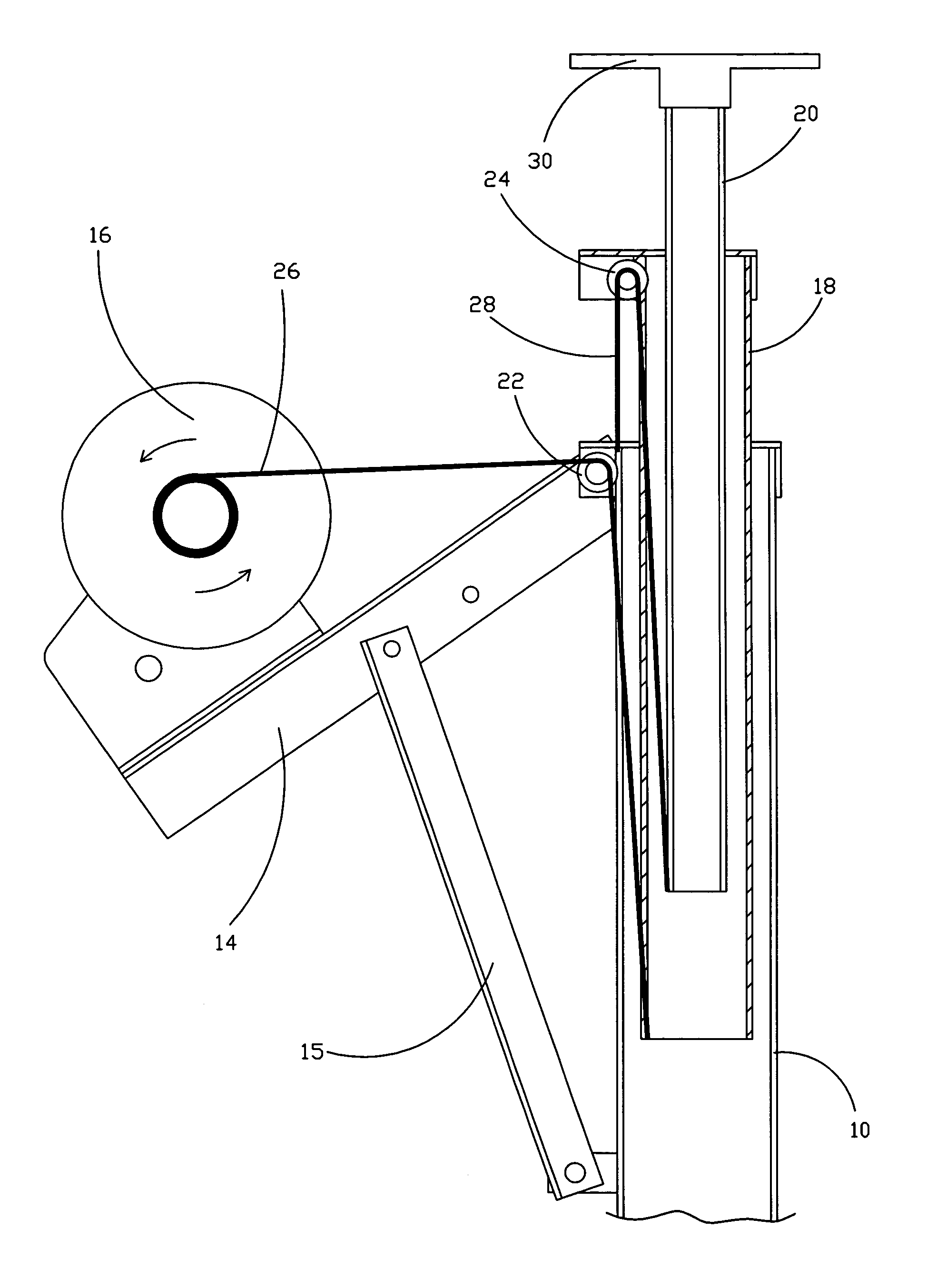
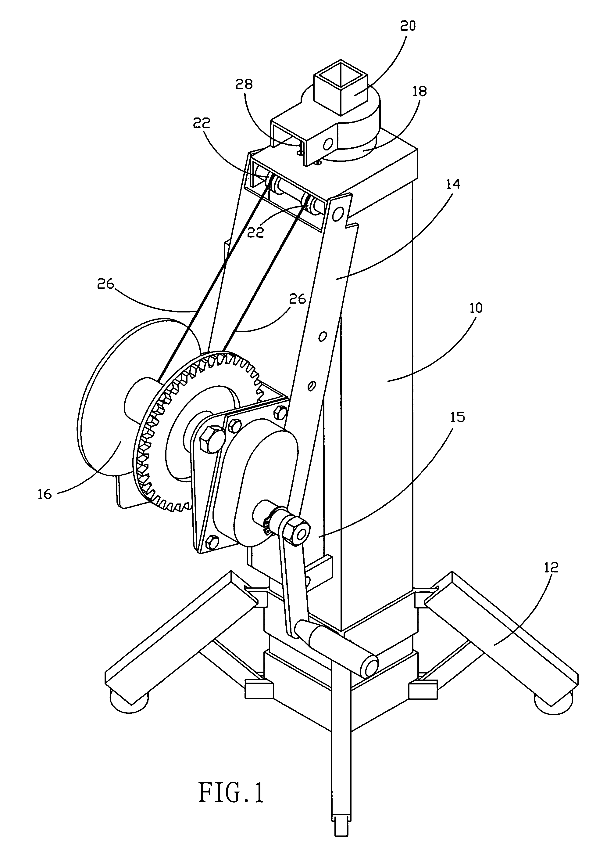
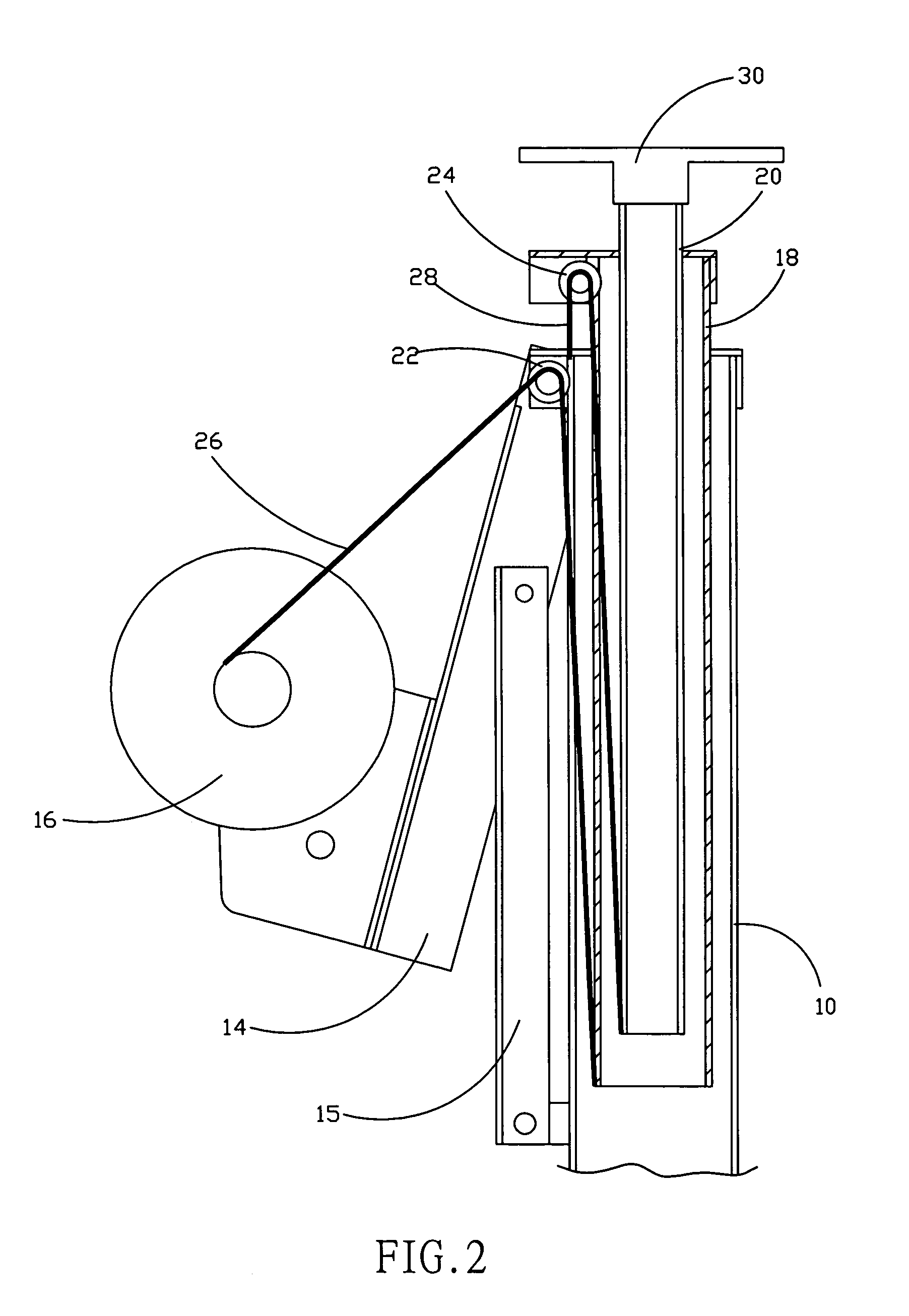
[0010]Referring to FIGS. 1 and 2, a lifter in accordance with the present invention is shown comprised of a wheeled carriage 12, a hollow main upright 10 mounted on the wheeled carriage 12 in vertical, a frame 14 pivoted to the hollow main upright 10, a hand winch 16 carried on the frame 14, a link 15 coupled between the bottom side of the hollow main upright 10 and a middle part of the frame 14, a hollow auxiliary upright 18 axially (vertically) movably mounted in the hollow main upright 10, a lifting upright 20 axially (vertically) movably mounted in the hollow auxiliary upright 18, a platform 30 fixedly provided at the top side of the lifting upright 20, a first pair of pulleys 22 bilaterally provided near the top of the hollow main upright 10 and arranged in parallel, a second pair of pulleys 24 bilaterally provided near the top of the hollow auxiliary upright 18 and arranged in parallel, two first cables 26 each having one end fixedly fastened to the winch 16 and the other end ...


PUM


Abstract

A lifter is constructed to include a hollow main upright, a frame pivoted to the main upright to carry a hand winch, a link coupled between the frame and the main upright, a hollow auxiliary upright axially movably mounted in the hollow main upright, a lifting upright axially movably mounted in the hollow auxiliary upright, two first pulley blocks coupled between the hand winch and the hollow auxiliary upright and adapted to lift the hollow auxiliary upright upon operation of the hand winch, and two second pulley blocks coupled between the hollow main upright and the lifting upright and adapted to lift the lifting upright upon operation of the hand winch after the hollow auxiliary upright has been extended out of the hollow main upright.

Description

BACKGROUND OF THE INVENTION[0001]1. Field of the Invention[0002]The present invention relates to a lifter for lifting a heavy load and, more particularly, to such a lifter, which is safe and durable in use.[0003]2. Description of the Related Art[0004]When lifting weights in a narrow place where a tower host or crane is not workable, a lifter may be used. Various lifters have been disclosed. There is known a lifter, which is comprised of a lifting main unit, a motor, and a transmission gearbox. The lifting main unit comprises an outer tube, and a telescopic tube mounted in the outer tube. The telescopic tube is formed of three inner tubes that slide one inside another. Each inner tube has the top and bottom sides respectively mounted with a pulley. The gearbox is coupled to the motor and adapted to rotate a winch, causing the winch to roll up or let off a cable, which has one end fastened to the winch and the other end extended in proper order through the pulleys at the top and botto...

Claims


Application Information

Patent Timeline
Patent Type & Authority Patents(United States)
IPC IPC(8): B66F3/00
CPCB66F3/00
Inventor HUANG, CHIN-PIAO
Owner HUANG CHIN PIAO
Learn More