Pneumatic cot for use with emergency vehicles

a pneumatic cot and emergency vehicle technology, applied in the field of wheeled cots, can solve problems such as unsuitable stairs, and achieve the effects of reducing the amount of space occupied in the ambulance, limiting the travel of the cot, and reducing the weight of the overall co

Inactive Publication Date: 2005-09-13
STRYKER CORP
View PDF13 Cites 42 Cited by
  • Summary
  • Abstract
  • Description
  • Claims
  • Application Information

AI Technical Summary

Benefits of technology

[0015]It is an object of some embodiments of the present invention to provide an ambulance cot which does not lock in the upright position, but instead provides an air-cushioned ride.
[0018]The emergency vehicle cot has a tubular frame made of a light-weight material to which is attached a litter. One unique aspect of the present invention is that the tubular frame also serves as the reservoir for the pneumatic system, thereby eliminating the need for an additional tank which can limit the travel of the cot. The incorporated reservoir also reduces the weight of the overall cot.
[0019]The wheeled cot is designed to be transported in a retracted position in an ambulance and then extended when removed from the ambulance and when transporting a patient on the ground. When the cot is desired to be placed back into the ambulance, the wheeled portion is retracted so as to reduce the amount of space occupied in the ambulance. The retraction and extension and the height of the cot is controlled by a pneumatic system utilizing a ram attached to a scissors frame.
[0020]Unlike some cots, however, when this cot is in a fully extended position, it does not lock in that position, but instead is maintained in that position by pneumatic pressure. The advantage to this arrangement is that the pneumatic pressure acts as a shock absorber to reduce the impact on the patient from vibrations and bumps encountered by the ambulance or when transporting the patient on the ground.
[0022]One of the embodiments of the cot anticipates a set of tracks which are applied over the wheels of the cot. These tracks smooth the transitions between the steps and other obstacles thereby allowing the patient to be transported more comfortably over uneven terrain. To assist in steering the cot when it is in the tank track mode, a hand brake is utilized.

Problems solved by technology

However, this wheel assembly, although providing for added mobility on flat surfaces, is not well suited for stairs.
In addition, as the cot is wheeled down the stairs, the patient is inclined and the vibration of the wheels bouncing down each stair not only causes pain, but may also result in further injury if the patient is inadvertently allowed to slide off of the cot, particularly if not properly restrained.

Method used


Image

  • Pneumatic cot for use with emergency vehicles
  • Pneumatic cot for use with emergency vehicles
  • Pneumatic cot for use with emergency vehicles

Examples


Embodiment Construction

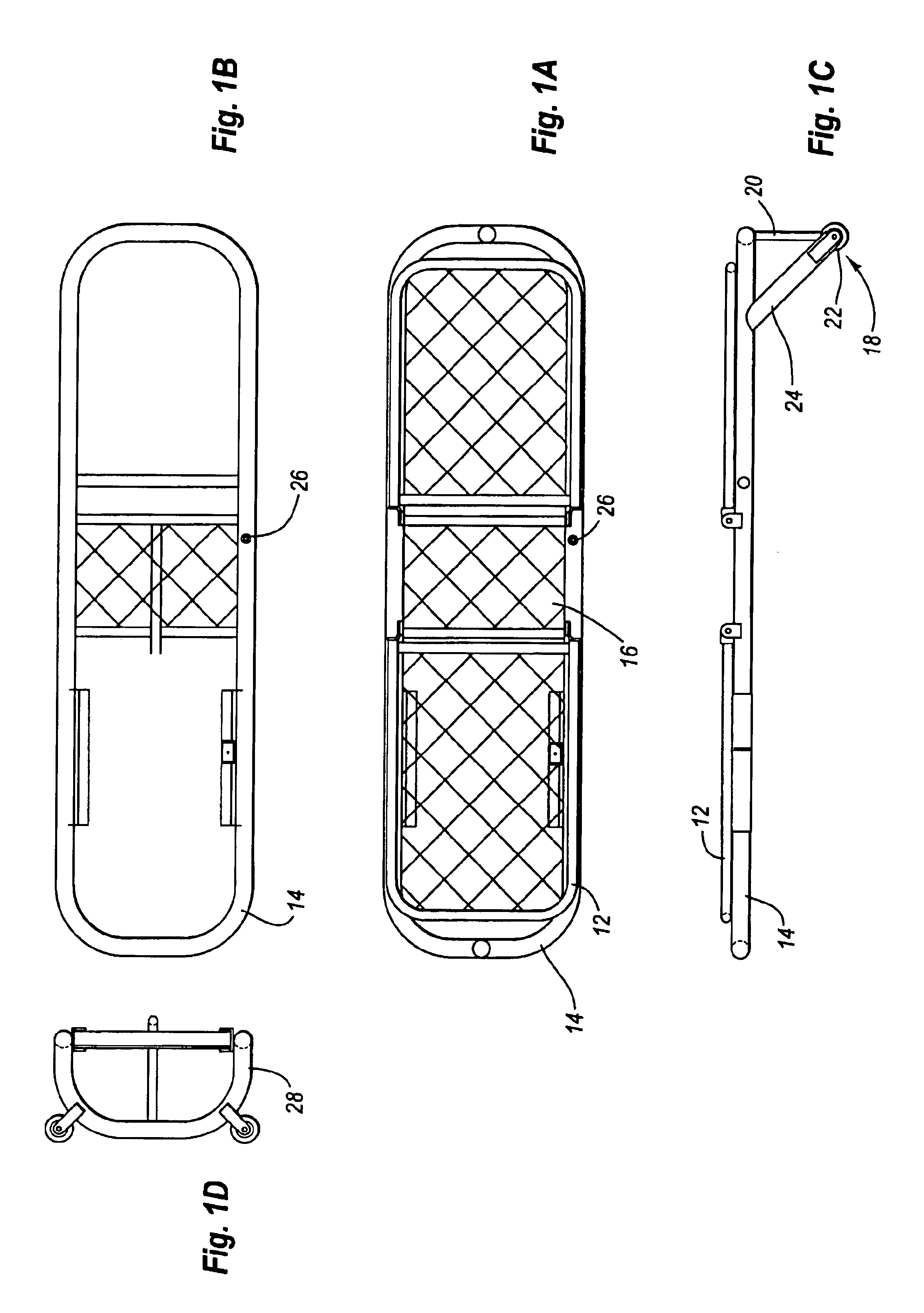
[0025]Turning now to FIG. 1, two plan views and one elevational view of the present invention are provided. A litter 12 is shown in the lower plan view labeled 1A attached to and placed on top of a cot litter support 14. Litter 12 is attached to cot litter support 14 at a central section 16. Central section 16 has at either side a pivoting attachment for the reminder of litter 12. As a result, both the left and right sides of litter 12 may be inclined to aid a patient in remaining on the litter when the litter is being transported down a stairwell or over inclined terrain. There are also medical reasons why litter 12 may be inclined and the present invention allows either side to be partially inclined to meet the needs of the patient.

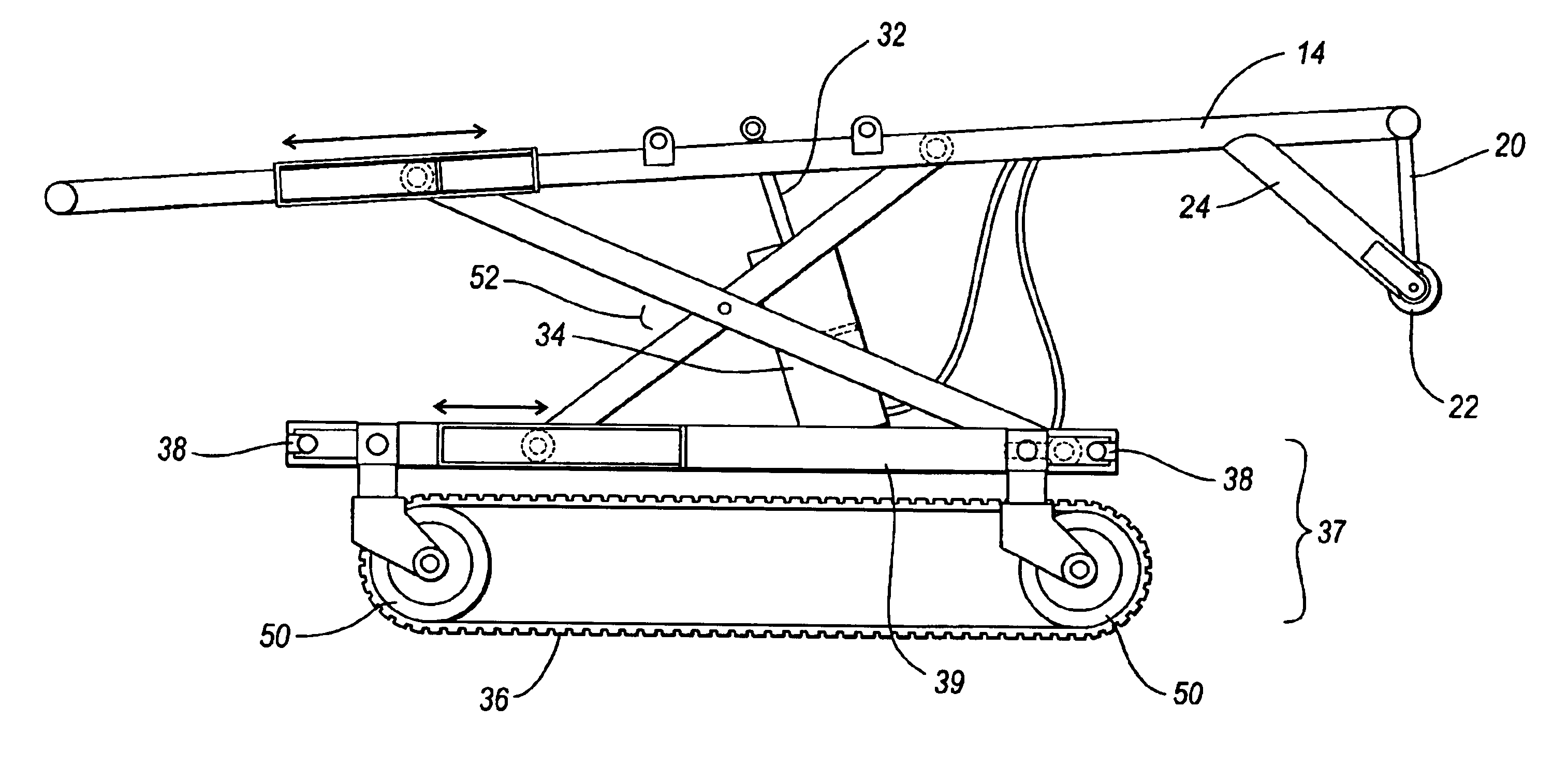
[0026]As can be seen in FIG. 1C, a vehicle entry assembly 18 is provided having a pivot arm 20, a wheel 22, and a retracting arm 24. The entire vehicle entry assembly can be retracted into the bottom of the cot to lower the profile of the cot, but may t...


PUM


Abstract

An ambulance cot is provided having a wheeled carriage, a frame for mounting the wheels, a horizontally oriented patient litter supported from the wheeled carriage and variable, pneumatically powered height scissors frame. The pneumatic actuator is designed to give a patient air-ride transportation and an adjustable height litter for lifting a patient from the ground. The patient litter has a pivoting hinge for transporting a patient down stairs. This pivot will allow the stretcher to pivot to a horizontal angle while going down stairs, for patient support and ease of transportation for the operator below. One embodiment has tracks attached over the wheels to provide a more stable and smooth ride as the cot is moved down stairs. Another embodiment comprises a translational trolley configuration. A hand brake is mounted on the patient litter for braking the tank-like motion of the tracks.

Description

FIELD OF THE INVENTION[0001]The present invention is a wheeled cot, and in particular an emergency vehicle cot is provided having a wheeled carriage, a frame for mounting the wheels, a horizontally oriented patient litter supported from the wheeled carriage by a scissors mechanism and a pneumatic ram to vary the height of the litter.BACKGROUND[0002]Early ambulance cots were cloth stretched between two long poles. Adding four wheels made cots easier to move to ambulances or fire and rescue trucks. Two additional wheels not in contact with the ground were eventually added to the loading end to make it possible to wheel the cot to the vehicle and engage the extra wheels with the floor of the vehicle before taking the weight off of the ground wheels. However, this wheel assembly, although providing for added mobility on flat surfaces, is not well suited for stairs. In addition, as the cot is wheeled down the stairs, the patient is inclined and the vibration of the wheels bouncing down e...

Claims


Application Information

Patent Timeline
Patent Type & Authority Patents(United States)
IPC IPC(8): A61G1/00A61G1/02A61G5/04A61G5/06A61G7/012A61G5/00A61G7/015A61G7/00A61G7/08A61G7/002A61G1/06
CPCA61G1/0293A61G1/0567A61G1/0212A61G1/0225A61G1/0287A61G1/0281A61G5/04A61G5/061A61G5/066A61G7/012A61G7/015A61G7/08A61G2001/042A61G1/042
Inventor WALKINGSHAW, NATHAN R.
Owner STRYKER CORP
Why Eureka
Try Eureka