Chamber having a protective layer

a protective layer and chamber technology, applied in the direction of coatings, printing, electrical equipment, etc., can solve the problems of reliability and material compatibility issues, catastrophic failure of the printhead, and material degradation coming into contact with such inks

Inactive Publication Date: 2005-09-13
HEWLETT PACKARD DEV CO LP
View PDF11 Cites 26 Cited by
  • Summary
  • Abstract
  • Description
  • Claims
  • Application Information

AI Technical Summary

Benefits of technology

[0005]A chamber includes a substrate, a chamber layer disposed on the substrate that defines the sidewalls of the chamber, and the chamber layer has a chamber surface. The chamber has an area in the plane formed by the chamber surface in the range from about 1 square micrometer to about 10,000 square micrometers. The chamber also includes an orifice layer dis

Problems solved by technology

This increase in organic content typically leads to inks exhibiting a more corrosive nature, potentially resulting in the degradation of the materials coming into contact with such inks.
Degradation of these materials by more corrosive inks raises reliability and material compatibility issues.
These material compatibility issues generally relate to all the materials the ink comes in contact with.
Thus, degradation of these materials can lead to potentially catastrophic failures of the printhead.
The interaction of these low molecular weight additives and the components of the ink may give rise to a weakening of the substrate/polymer film interface.
Delamination of the polymer film from the substrate surface may lead to ink penetrating to regions where active circuitry is located leading to the potential for either corrosion or electrical shorting, or both, all of w

Method used


Image

  • Chamber having a protective layer
  • Chamber having a protective layer
  • Chamber having a protective layer

Examples


Embodiment Construction

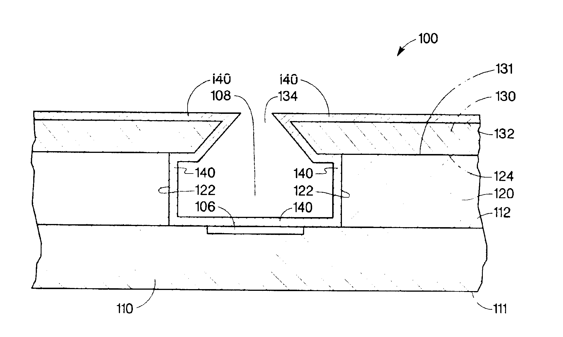
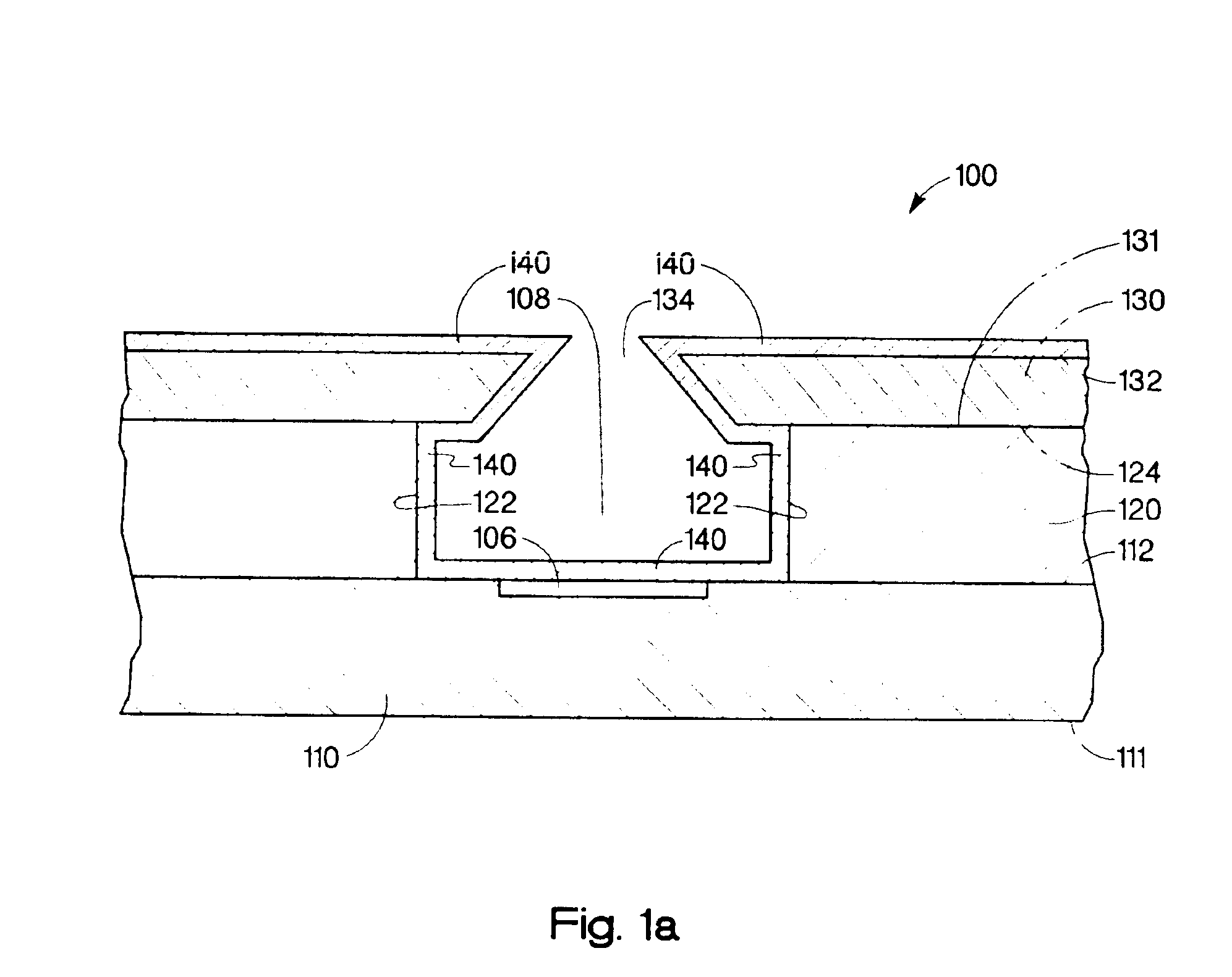
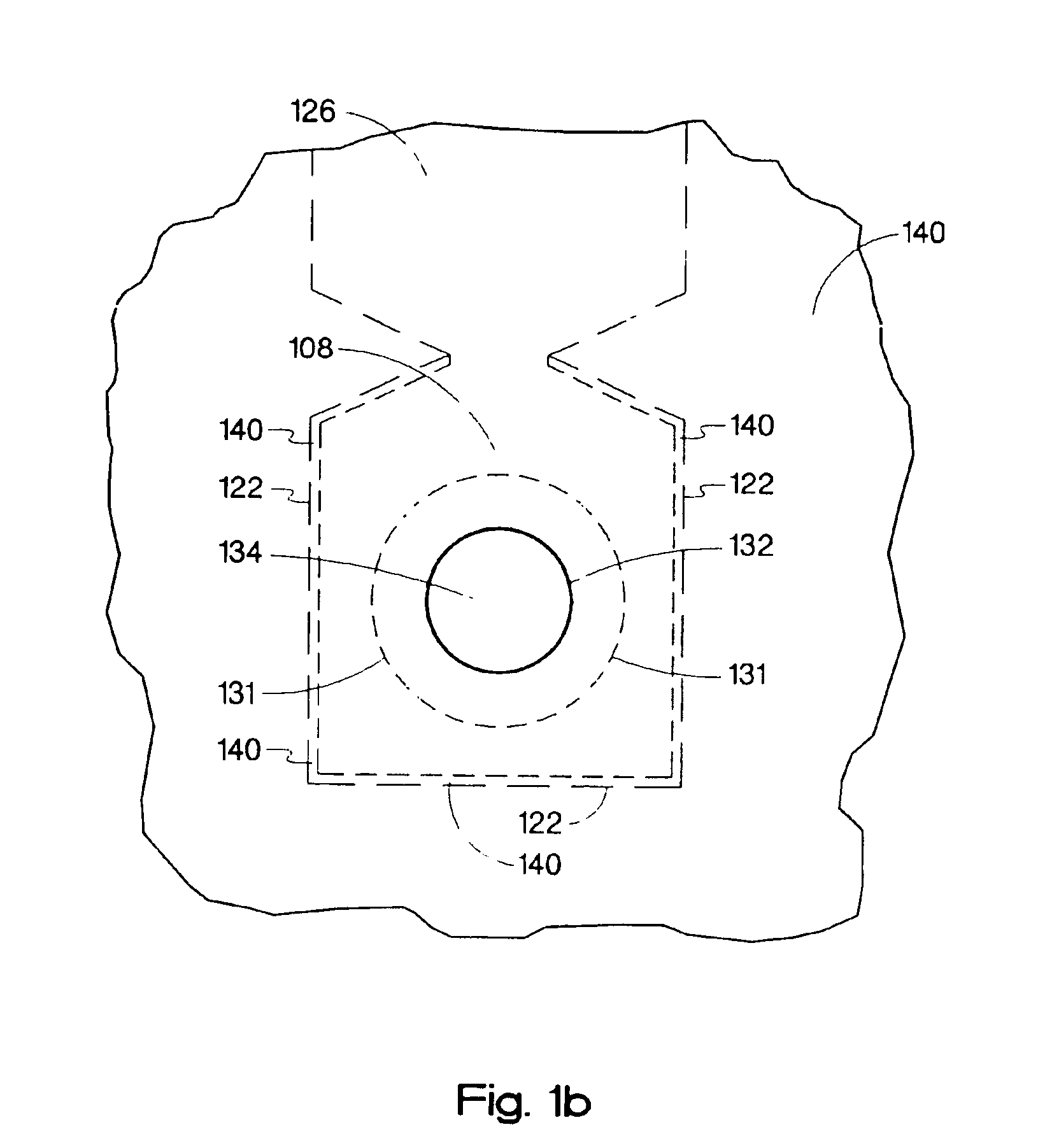
[0017]Referring to FIG. 1a, an embodiment of the present invention is shown in a simplified cross-sectional view. In this embodiment, fluid ejector head 100 includes protective layer 140 providing moisture and corrosion protection to surrounding areas from fluid contained within fluid ejection chamber 108. In this embodiment, substrate 110 is a silicon wafer having a thickness of about 300-700 micrometers. In alternative embodiments, other materials may also be utilized for substrate 110, such as, various glasses, aluminum oxide, polyimide substrates, silicon carbide, and gallium arsenide. Accordingly, the present invention is not intended to be limited to those devices fabricated in silicon semiconductor materials.

[0018]Fluid ejector generator 106 is formed on substrate 110. In this embodiment, fluid ejector generator 106 is a thermal resistor. In alternate embodiments, other fluid ejector generators such as piezoelectric, ultrasonic, or electrostatic generators may also be utilize...


PUM

PropertyMeasurementUnit
Thicknessaaaaaaaaaa
Thicknessaaaaaaaaaa
Lengthaaaaaaaaaa

Abstract

A chamber includes a substrate, a chamber layer disposed on the substrate that defines the sidewalls of the chamber, and the chamber layer has a chamber surface. The chamber has an area in the plane formed by the chamber surface in the range from about 1 square micrometer to about 10,000 square micrometers. The chamber also includes an orifice layer disposed over the chamber layer. The orifice layer has a first and second orifice surface and a bore wherein the bore has an area in the plane formed by the first orifice surface less than the chamber area. The chamber further includes a protective layer deposited, through the bore, on the sidewalls of the chamber layer and a portion of the first orifice surface.

Description

BACKGROUNDDescription of the Art[0001]Fluid ejection cartridges typically include a fluid reservoir that is fluidically coupled to a substrate. The substrate normally contains an energy-generating element that generates the force necessary for ejecting the fluid through one or more nozzles. Two widely used energy-generating elements are thermal resistors and piezoelectric elements. The former rapidly heats a component in the fluid above its boiling point creating a bubble causing ejection of a drop of the fluid. The latter utilizes a voltage pulse to move a membrane that displaces the fluid resulting in ejection of a drop of the fluid.[0002]Currently there is a wide variety of highly-efficient inkjet printing systems in use. These systems are capable of dispensing ink in a rapid and accurate manner. However, there is also a demand by consumers for ever-increasing improvements in reliability and image quality, while providing systems at lower cost to the consumer. In an effort to red...

Claims


Application Information

Patent Timeline
IPC IPC(8): B41J2/14B41J2/16B05C5/00B41J2/05
CPCB41J2/1404B41J2/1433B41J2/1603B41J2/1606B41J2/1631B41J2/1634B41J2/1642B41J2/1646B41J2/162Y10T29/49401
Inventor FARTASH, ARJANG
Owner HEWLETT PACKARD DEV CO LP
Why Eureka
Try Eureka