Packaging structure for liquid container and unsealing method therefor

a liquid container and packaging technology, applied in the field of liquid containers, can solve the problems of affecting the use of the user's hand or object, the action of turning the wrist or turning the wrist is difficult for children, aged persons, or users, and achieves the effect of avoiding ink leakag

Inactive Publication Date: 2005-09-13
CANON KK
View PDF13 Cites 18 Cited by
  • Summary
  • Abstract
  • Description
  • Claims
  • Application Information

AI Technical Summary

Benefits of technology

[0014]The present invention is designed with a view to solving the problems discussed above. It is an object of the invention to provide a highly reliable packaging structure for a liquid container, which is capable of preventing ink splashes from the ink supply port when it is unsealed, and also, unsealed easily by anyone.
[0016]With the packaging structure thus arranged, when the user detaches the first part from the second part of the covering member, which is formed to be circular to cover the outer circumference of the liquid container, the covering member is broken to separate the first part and the second part, thus unsealing the liquid supply port. With the structure of the kind, unsealing is not effectuated by directly removing means for sealing a liquid supply port, but by the detaching operation of the second part to unseal it indirectly. Therefore, irrespective of the impetus of unsealing carried out by each individual user, unsealing is possible at a constant impetus. Also, the unsealing impetus can be controlled by the strength of material used for the first part to make the set up of the prevention of liquid splash possible at the time of unsealing.
[0017]In a case of the packaging thus structured, it is preferable to adopt the material and shape of the first part so as to be maintained along the outer circumference of the liquid container even when the second part is detached from the first part. With the structure thus arranged, the first part remains on the outer circumference of the liquid container after the detachment of the second part. Therefore, the first part does not fall off from the liquid container by the detachment of the second part. Further, it may be possible to apply a weak bonding between the first part and the liquid container, which is just good enough to keep the first part not to fall off. Even with such structure, the first part does not fall off from the liquid container after the detachment of the second part as described above. In other words, in accordance with the aforesaid structure, the first part is not bonded to the liquid container with such strong bonding force as to keep air tightness as in the conventional example, but with weak bonding force. Therefore, the user is not required to exercise any vigorous pull when the first part is removed. Consequently, there occurs no splash of liquid adhering to the means for sealing the liquid supply port.
[0023]Also, when the liquid container is provided with an atmosphere communication port for enabling the space in the container to be communicated with the air outside, it may be possible to provide further an elastic member to cover the atmosphere communication port. In this case, such elastic member that covers the atmosphere communication port is provided for the second part. Then, it is made possible to set up an unsealing order so that the ink supply port is open after the atmosphere communication port is open. In this way, it becomes possible to make the possibility smaller still that ink leaks at the time of unsealing the ink tank. Furthermore, even if the structure is such that the atmosphere communication port is bonded to the second part for sealing it, it is still possible to set up the unsealing order so that the ink supply port is open after the atmosphere communication is open, thus the fear of ink leakage as described above being made smaller still.

Problems solved by technology

As a result, there is a fear that the ink, which has been airtightly kept by the sealing member, may splash to stain the user's hand or objects that surround the ink tank in some cases.
Therefore, this action of turning the wrist or “twisting” is a difficult one for children, aged persons, or a user who has difficulty in using his hand or wrist.

Method used


Image

  • Packaging structure for liquid container and unsealing method therefor
  • Packaging structure for liquid container and unsealing method therefor
  • Packaging structure for liquid container and unsealing method therefor

Examples


first embodiment

(First Embodiment)

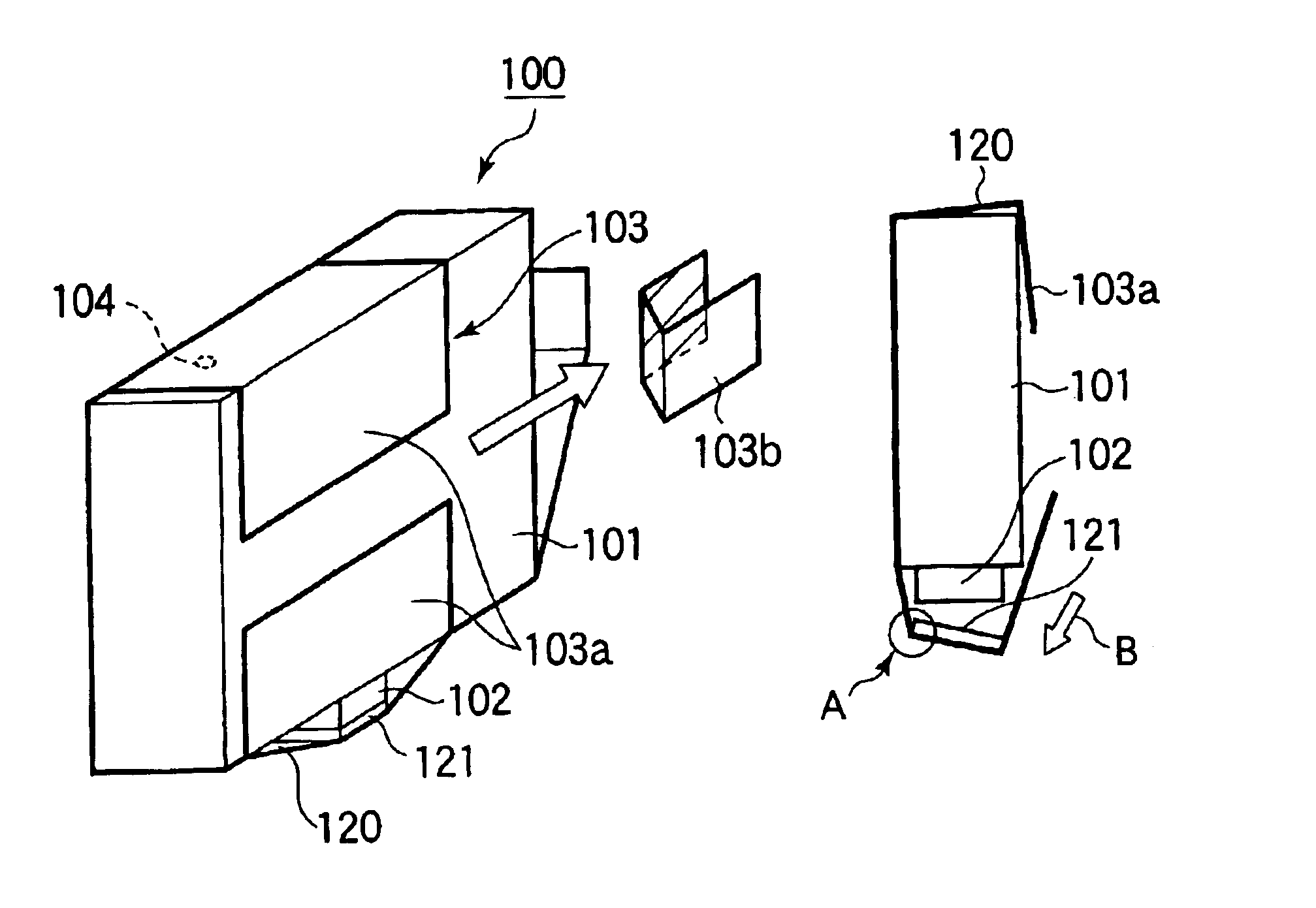
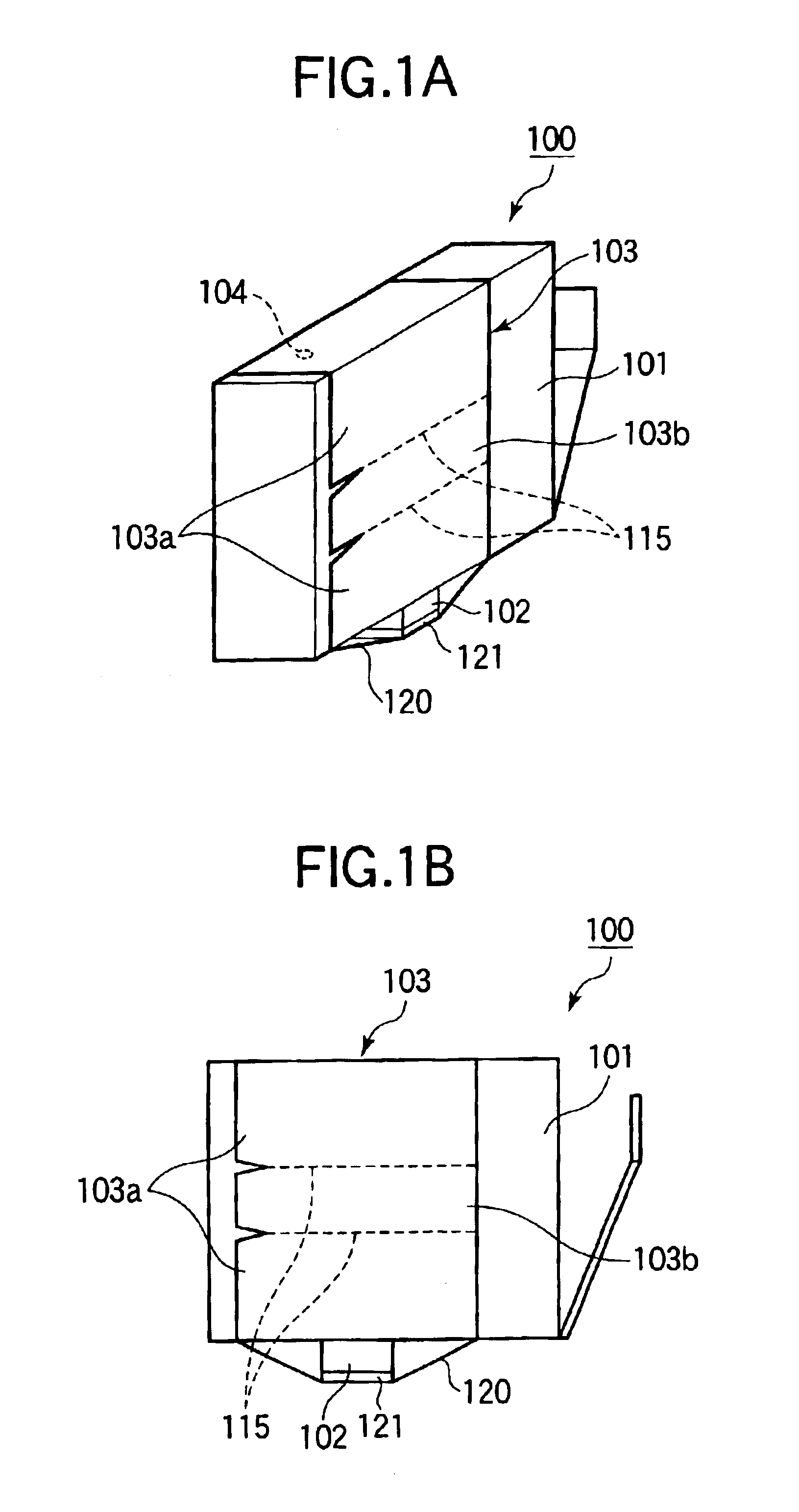
[0039]FIGS. 1A and 1B are views that illustrate the entire structure of an ink tank in accordance with a first embodiment of the present invention; FIG. 1A is a perspective view of the ink tank; and FIG. 1B is a side view of the ink tank.

[0040]An ink tank100 shown in FIGS. 1A and 1B is provided with an ink container 101 that contains ink; an ink supply port 102 that supplies ink to the outside (for example, an ink jet recording head); an atmosphere communication port 104 that induces and exhausts the air; and a covering member 103 that covers the ink supply port 102, and also, covers the entire body of the ink container 101. The covering member 103 is structured with a first part 103a and a second part 103b. Further, the first part 103a is provided with the cap 121 that keeps the ink supply port 102 airtight, and a wrapping member 120 that wraps the ink container 101 including the cap 121.

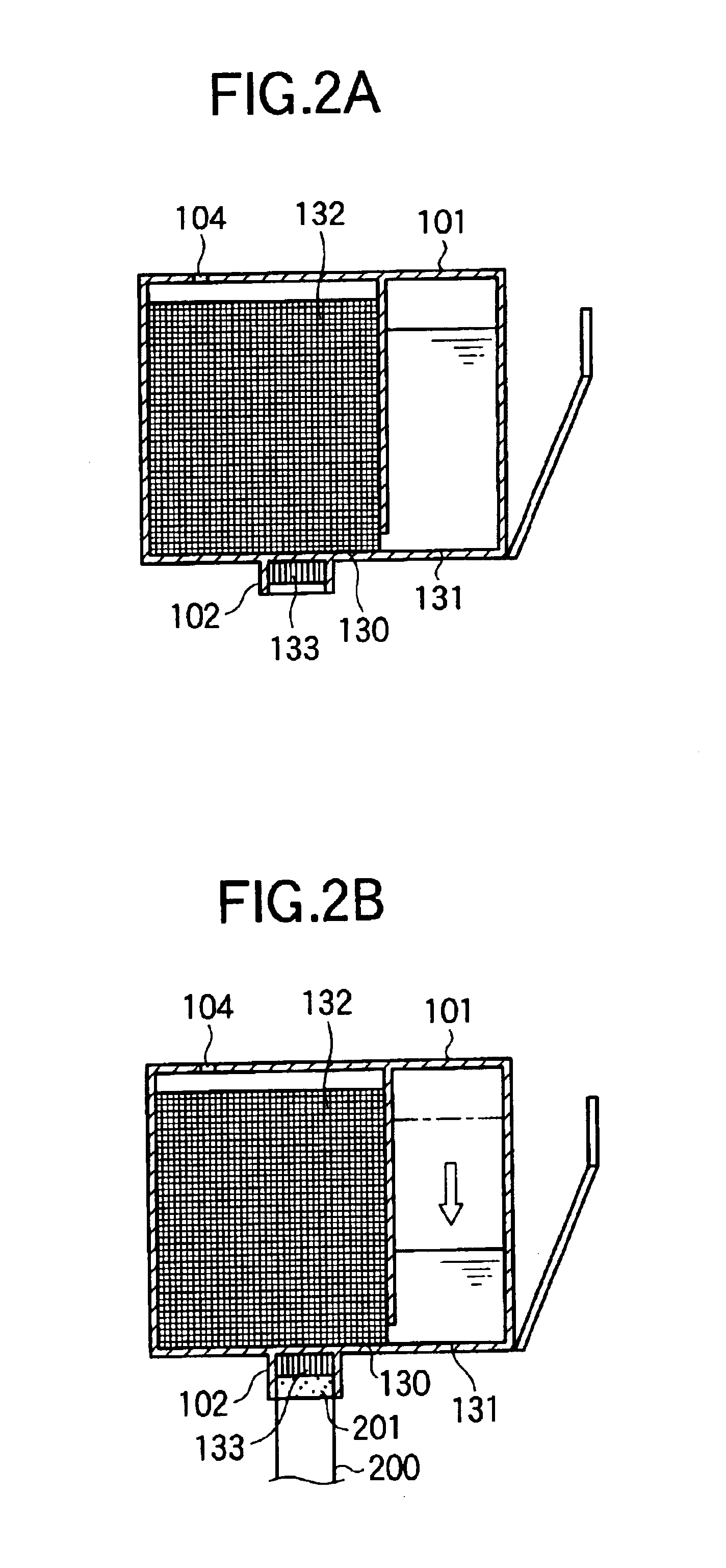
[0041]FIGS. 2A and 2B are cross-sectional views that show the ink container 1...

second embodiment

(Second Embodiment)

[0064]Next, with reference to FIG. 7, the description will be made of a second embodiment of the ink tank in accordance with the present invention. Here, what differs from the first embodiment will be described mainly. FIG. 7 is a perspective view that shows the packaging structure of an ink tank in accordance with the second embodiment of the present invention.

[0065]For the ink tank 100 in a mode as shown in FIG. 7, the covering member 103 is structured to be circular by bonding the first part 103a and the second part 103b thereof. The wrapping member 120 that constitutes the first part 103a is formed by shrink film with the exception of the cap 121. Then, the film, which is provided with adhesive agent, forms the second part 103b. Along the contour of the flat rectangular ink container 101, the wrapping member 120 is provided in the U-letter form. Both ends of the wrapping member 120 face each other on the side face of the ink container 101 (on the surface havin...

third embodiment

(Third Embodiment)

[0068]Next, with reference to FIG. 8, the description will be made of a third embodiment of the ink tank in accordance with the present invention. Here, what differs from the first and second embodiments will be described mainly. FIG. 8 is a perspective view that shows the packaging structure of the ink tank in accordance with the third embodiment.

[0069]For the ink tank 100 in a mode as shown in FIG. 8, the covering member 103 is structured to be circular by bonding the first part 103a and the second part 103b thereof. The wrapping member 120 that constitutes the first part 103a is formed by shrink film with the exception of the cap 121. Then, the film, which is provided with adhesive agent, forms the second part 103b.

[0070]The present embodiment is different from the second embodiment in the method of bonding adopted for the first part 103a and the second part 103b. In other words, the first part 103a (wrapping member 120) covers the ink container 101 along the co...


PUM


Abstract

A packaging structure of a liquid container, which is provided with a liquid containing portion for containing liquid and a liquid supply port for supplying liquid, comprises a covering member for covering the liquid supply port. For this packaging structure, the covering member is a circular member formed by a first part and a second part to cover the outer circumference of the liquid container, and the first part is provided with means for sealing the liquid supply port, and the second part is made detachable from the first part, and the circular form of the covering member is broken by the detachment of the second part. With the packaging structure thus arranged, when the user detaches the first part from the second part of the covering member, the covering member is broken to separate the first part and the second part, thus unsealing the liquid supply port. Therefore, unsealing is possible at a constant impetus irrespective of the impetus of unsealing carried out by each individual user. Also, the unsealing impetus can be controlled by the strength of material used for the first part to make the set up of the prevention of liquid splash possible at the time of unsealing.

Description

BACKGROUND OF THE INVENTION[0001]1. Field of the Invention[0002]The present invention relates to a liquid container for containing recording liquid, such as ink, for example, which is detachably mountable on an ink jet recording apparatus. More particularly, the invention relates to the packaging structure of such liquid container.[0003]2. Related Background Art[0004]Conventionally, for example, there has been proposed the exchangeable ink tank for supplying ink to an ink jet recording head through an ink supply tube, which is structured separately from the ink jet recording head that records on a recording medium by discharging ink. The exchangeable ink tank is provided with an ink supply port for supply ink to the recording head, and an atmosphere communication port that enables the inside of the ink tank to be communicated with the air outside. In many cases, the structure is arranged so as to provide an ink absorbent for the inside of the housing thereof, and retain ink in the i...

Claims


Application Information

Patent Timeline
Patent Type & Authority Patents(United States)
IPC IPC(8): B41J2/175B65D71/08B65D77/20
CPCB41J2/17533B41J2/1754
Inventor NANJO, TATSUO
Owner CANON KK
Why Eureka
Try Eureka