Cable force monitoring device for attached-type stay cable

A monitoring device and an attached technology, applied in the direction of measuring device, adopting optical device, measuring the force applied to the control element, etc., can solve the problems of insufficiency, low precision, lack of theoretical basis, etc., and achieve convenient maintenance and replacement, The effect of reducing maintenance costs and improving connection strength

Active Publication Date: 2011-08-24
CHINA RAILWAY BRIDGE SCI RES INST LTD +1
View PDF5 Cites 32 Cited by
  • Summary
  • Abstract
  • Description
  • Claims
  • Application Information

AI Technical Summary

Benefits of technology

This invention relates to an improved type of semirigid touch connector that prevents physical damages on cables during use without compromising their function or performance. Additionally it provides excellent protection against electrical noise caused by lightning strikes. Overall this design makes connecting electronic devices more reliable over longer periods of time compared with traditional methods like crimped connections.

Problems solved by technology

Technological Problem addressed in this patented text relates to improving the reliability and accuracy of current methods for detecting forces applied over structures such as cords without damaging their integrity due to external factors like weather exposure. Current methods require expensive equipment and time-consumings, while new methods have improved performance compared to previous ones.

Method used


Image

  • Cable force monitoring device for attached-type stay cable
  • Cable force monitoring device for attached-type stay cable
  • Cable force monitoring device for attached-type stay cable

Examples


Embodiment Construction

[0041]Below in conjunction with embodiment and accompanying drawing, the present invention is further described, and this embodiment is a main span 1088m steel truss stiffened girder suspension bridge; In this embodiment, because bridge health monitoring system implementation project is arranged after the completion of the bridge, its suspension cable and anchor span cable The strand force monitoring subsystem needs to be constructed after the bridge is completed.

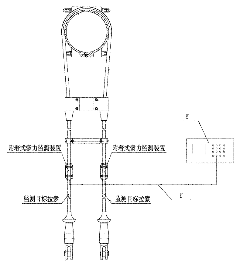
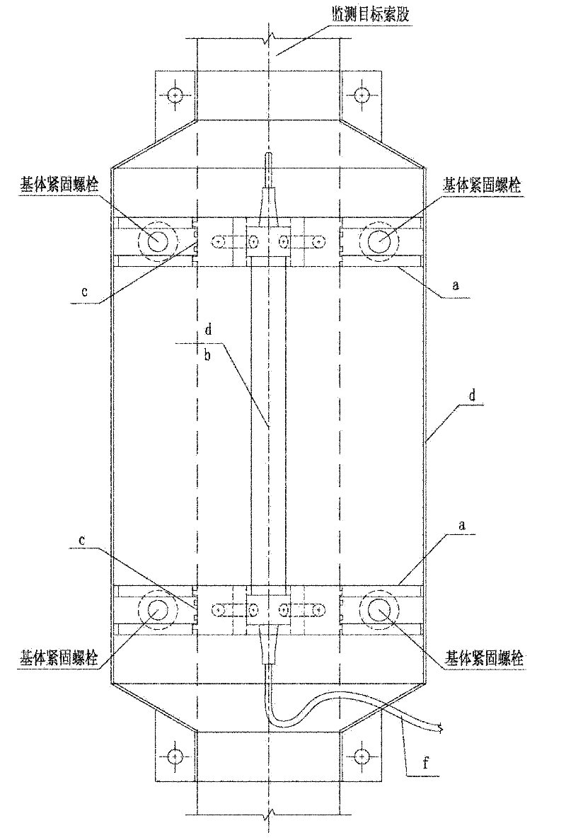
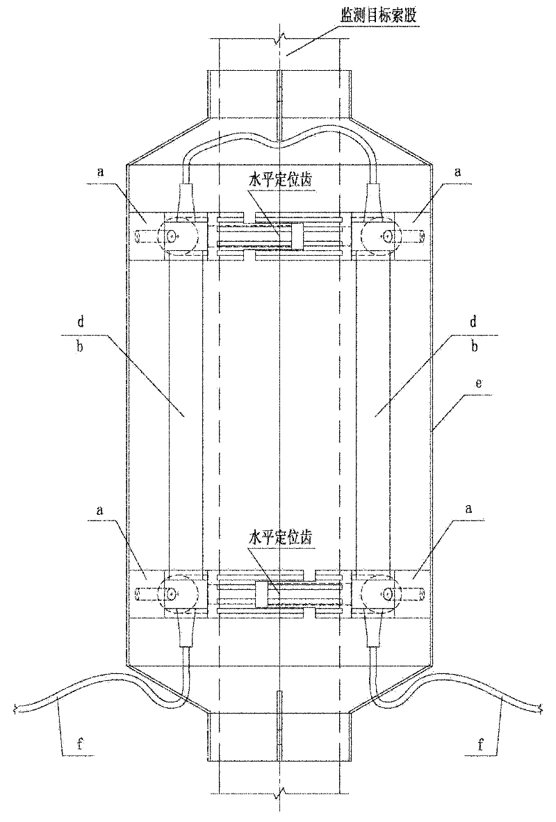
[0042] figure 1 It is the composition diagram of the monitoring system of the attached cable force monitoring device of the present invention, figure 2 It is the front view of the detailed schematic diagram of the key structure of the attached cable force monitoring device of the present invention, image 3 It is a side view of the detailed schematic diagram of the key structure of the attached cable force monitoring device of the present invention, Figure 4 It is a top view of the detailed schematic diagram of...


PUM


Abstract

The invention provides a cable force monitoring device for an attached-type stay cable. In the technical scheme of the invention, a reliable composite semi-rigid contact cohesion-type mechanical deformation transmitter is installed at the position of a fixed scale distance on a stay cable with a traditional structure; a temperature self-compensating fiber grating precision strain transducer is adhered to the surface of the stay cable through the composite semi-rigid contact cohesion-type mechanical deformation transmitter; and the axial strain caused by the change of the pulling force applied to the stay cable in a scale distance is measured; the axial strain of the stay cable is converted into optical signals through the fiber grating precision strain transducer, and the optical signals are transmitted to a collecting demodulation terminal through an optical cable for demodulation; and testing software automatically calculates the corresponding cable force variation value according to strain measurement data, stay cable cross section geometric parameters and mechanical property parameters of stay cable materials, and further the automatic real-time dynamic monitoring of the stay cable is realized.

Description


Claims


Application Information

Patent Timeline
Owner CHINA RAILWAY BRIDGE SCI RES INST LTD
Why Eureka
Try Eureka