Asymmetric aperture diaphragm placing structure for projection lens and projection type image display apparatus using the same

a technology of asymmetric aperture and placing structure, which is applied in the field of asymmetric aperture diaphragm placing structure of a projection lens, can solve the problems of low contrast, unrecognized structure for attaching such an asymmetric aperture diaphragm,

Inactive Publication Date: 2005-09-13
FUJI PHOTO OPTICAL CO LTD
View PDF5 Cites 7 Cited by
  • Summary
  • Abstract
  • Description
  • Claims
  • Application Information

AI Technical Summary

Benefits of technology

[0010]In view of the foregoing circumstances, it is an object of the present invention to provide an asymmetric aperture diaphragm placing structure for a projection lens, which can accurately position and secure an asymmetric aperture diaphragm having a diaphragm aperture asymmetrical abou

Problems solved by technology

However, a part of the light to become unnecessary light may be scattered by the mirror element surface, and thus formed scattering light may enter the projection lens and lower the contrast.
However, structures for attaching such an asymmetric aperture diaphragm to a lens chamber or the like, i.e., asymmetric aperture diaphragm placing structures, have not been disclosed yet.
When the diaphragm aperture of the asymmetric aperture dia

Method used


Image

  • Asymmetric aperture diaphragm placing structure for projection lens and projection type image display apparatus using the same
  • Asymmetric aperture diaphragm placing structure for projection lens and projection type image display apparatus using the same
  • Asymmetric aperture diaphragm placing structure for projection lens and projection type image display apparatus using the same

Examples


Embodiment Construction

[0022]In the following, embodiments of the present invention will be explained in detail with reference to the drawings.

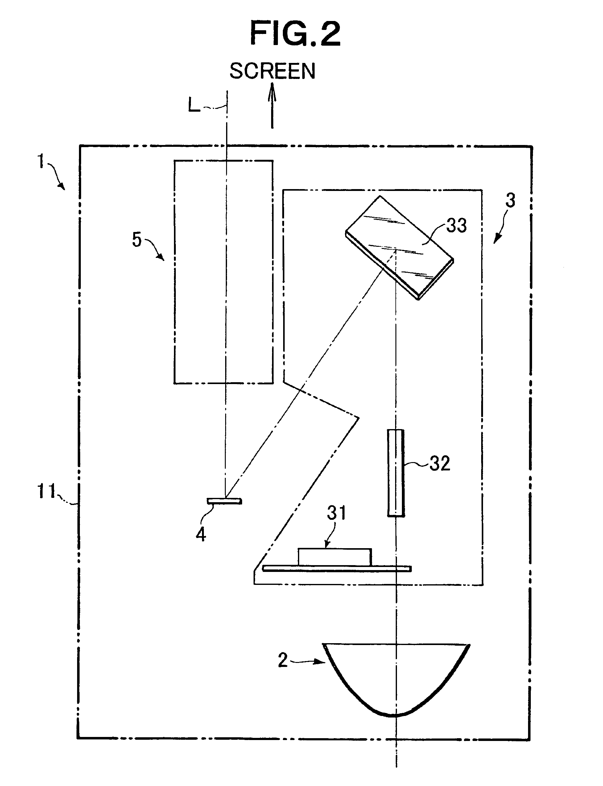
[0023]FIG. 2 is a view schematically showing the configuration of the projection type image display apparatus in accordance with an embodiment of the present invention.

[0024]As shown in FIG. 2, the projection type image display apparatus 1 in accordance with this embodiment, which is used as a video projector, for example, comprises a light source section 2, an illumination optical system 3 disposed in front of the light source section 2 in the optical axis direction, an image display 4 disposed in front of the illumination optical system 3 in the optical axis direction, and a projection lens system 5 disposed in front of the image display 4 in the optical axis direction, which are contained within a housing 11.

[0025]The illumination optical system 3 comprises a color wheel 31 for decomposing a luminous flux (white luminous flux) from the light source section 2 int...


PUM


Abstract

An asymmetric aperture diaphragm placing structure for a projection lens is provided for securing an asymmetric aperture diaphragm to a lens holder. The asymmetric aperture diaphragm includes a positioning part formed asymmetrical about the optical axis. The lens holder has a mating part adapted to engage the positioning part only in a state where the asymmetric aperture diaphragm is in a predetermined direction with respect to the optical axis. The asymmetric aperture diaphragm is secured to the lens holder in a state where the positioning part and the mating part engage each other.

Description

RELATED APPLICATIONS[0001]This application claims the priority of Japanese Patent Application No. 2002-314574 filed on Oct. 29, 2002, which is incorporated herein by reference.BACKGROUND OF THE INVENTION[0002]1. Field of the Invention[0003]The present invention relates to an asymmetric aperture diaphragm placing structure for a projection lens, which secures an asymmetric aperture diaphragm having an aperture asymmetrical about the optical axis of the projection lens to a lens holder such as a lens chamber holding the projection lens in a projection type image display apparatus comprising image display means such as digital micromirror device (hereinafter referred to as “DMD”), for example; and a projection type image display apparatus comprising such an asymmetric aperture diaphragm placing structure.[0004]2. Description of the Prior Art[0005]A projection type image display apparatus has conventionally been known, in which a DMD comprising a number of mirror elements with variable ...

Claims


Application Information

Patent Timeline
IPC IPC(8): G03B21/14G02B7/02G02B27/18G03B9/02G03B21/00H04N5/74
CPCG03B21/14G03B21/142
Inventor INAMOTO, MASAYUKI
Owner FUJI PHOTO OPTICAL CO LTD
Why Eureka
Try Eureka