Mixer for liquid chromatograph

Active Publication Date: 2005-09-13
SHIMADZU CORP
View PDF20 Cites 13 Cited by
  • Summary
  • Abstract
  • Description
  • Claims
  • Application Information

AI Technical Summary

Benefits of technology

[0005]The present invention aims at eliminating the above-mentioned drawbacks found in the related-art mixer. Accordingly, it is an object of the in

Problems solved by technology

In the case of such mixer, since balls for mixing are loaded into the interior of the mixer, the internal capacity thereof is large.
In order to mix together the plurality of liquids with high efficiency, there is required the optimum mixer capacity according to the flow quantities of

Method used


Image

  • Mixer for liquid chromatograph
  • Mixer for liquid chromatograph
  • Mixer for liquid chromatograph

Examples


Example

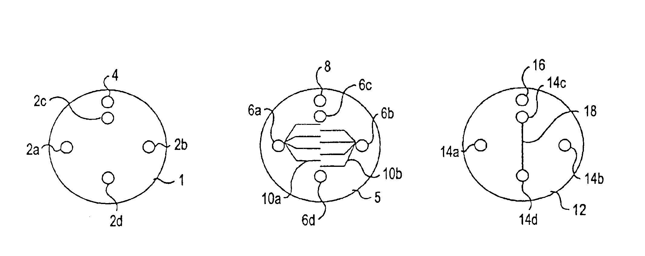
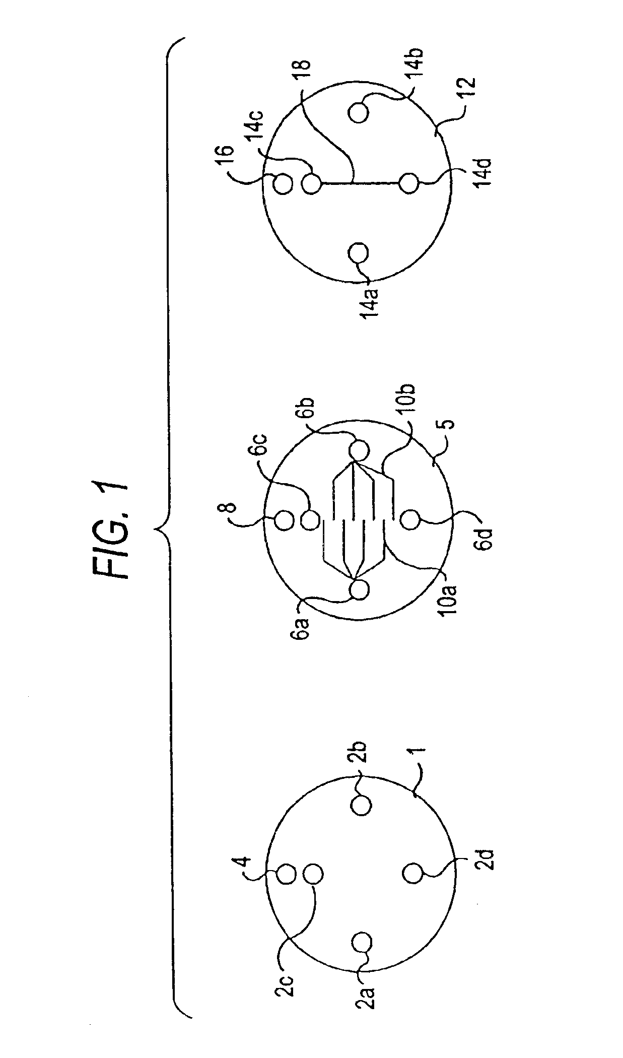
[0013]Now, description will be given below in detail of the mode for carrying out the invention with reference to the accompanying drawings. FIG. 1 is a schematic structure view of an embodiment of a mixing portion of a mixer for a liquid chromatograph according to the invention. Three metal plate materials 1, 5, and 12 provide a basic structure for the mixing portion. The metal plate material 1 includes four penetration holes 2a-2d and a positioning hole 4. The metal plate material 5 includes four penetration holes 6a-6d, a positioning hole 8, and two flow passages 10a, 10b. The metal plate material 12 includes four penetration holes 14a-14d, a positioning hole 16 and a flow passage 18. The metal plate materials 1, 5, and 12 are each a corrosion resistant metal plate (for example, SUS316) having a thickness of 2 mm or less. The positioning holes 4, 8 and 16 are all penetration holes and are respectively formed at the same positions in their associated metal plate materials 1, 5 and...


PUM

PropertyMeasurementUnit
Flow rateaaaaaaaaaa
Efficiencyaaaaaaaaaa

Abstract

Three metal plate materials, each having penetration holes, are united together in this order as a set at such positions that penetration holes can penetrate through the three metal plate materials so as to form a mixing portion. A plurality of sets, each having the mixing portion, are integrated together at such positions that all of the penetration holes can penetrate through the respective sets of plate materials. The mixing portions of the respective sets are connected in parallel to one another.

Description

BACKGROUND OF THE INVENTION[0001]1. Field of the Invention[0002]The present invention relates to a mixer for a liquid chromatograph and, in particular, to a mixer which is used to mix liquids together so as to make an eluent for gradient analysis.[0003]2. Description of the Related Art[0004]In a liquid chromatograph, there is made a gradient analysis in which the composition of an eluent is caused to vary continuously or in a stepped manner. In the gradient analysis, in order that two or more kinds of liquids are mixed together to thereby introduce a column as an eluent, a gradient eluting apparatus includes a mixer for mixing a plurality of liquids together. As the mixer, there is often used an apparatus of a flow-through type which does not include a movable part; for example, there is known an apparatus structured such that balls made of stainless steel are loaded into a pipe having an inside diameter of about 3 mm and a length of about 50 mm. This type of mixer is composed of a ...

Claims


Application Information

Patent Timeline
IPC IPC(8): B01F13/00B01F13/10G01N30/00G01N30/34G01N30/02
CPCB01F13/0059B01F13/1013B01F13/1022G01N30/34G01N30/02G01N2030/347B01D15/166Y10S366/03B01F33/30B01F33/813B01F33/81
Inventor ASO, YOSHIAKI
Owner SHIMADZU CORP
Why Eureka
Try Eureka